Pickup structure and use method thereof

A component and reflective surface technology, applied in the direction of microphone mouth/microphone accessories, etc., can solve the problems of high manufacturing cost, extended sound pickup distance, poor sound pickup effect, etc., so as to avoid complex circuits and algorithm software, avoid The increase in manufacturing costs and the effect of extending the effective pickup distance

Pending Publication Date: 2022-07-29
易科技术(东莞)有限公司
View PDF0 Cites 0 Cited by
  • Summary
  • Abstract
  • Description
  • Claims
  • Application Information

AI Technical Summary

Problems solved by technology

[0004] First, the effective sound pickup distance is relatively long, and it is difficult for the sound from the sound source in the intended direction of use to be fully collected into the sound pickup microphone head of the sound pickup structure. The farther the microphone is, the worse the pickup effect will be;
[0005] Second, but corresponding to the first, in order to improve the pickup distance, manufacturers usually increase the sensitivity of the pickup microphone. The sound also has high sensitivity, leading to positive feedback phenomenon, that is, the sound will produce sharp and harsh sound;
[0006] Third, the directional sound pickup effect is poor. In some usage scenarios, the sound pickup structure that picks up sound in all directions or in a larger range may pick up too much noise, which cannot meet the requirements for use. For this, manufacturers generally use circuit and various algorithm software to eliminate noise, but the cost of this method is too high;
[0007] In general, the existing sound pickup structure is difficult to avoid the occurrence of positive feedback phenomenon while prolonging the sound pickup distance on the one hand, and it is difficult to avoid excessive manufacturing costs while improving the directional sound pickup effect

Method used


Image

  • Pickup structure and use method thereof
  • Pickup structure and use method thereof
  • Pickup structure and use method thereof

Examples


Embodiment approach

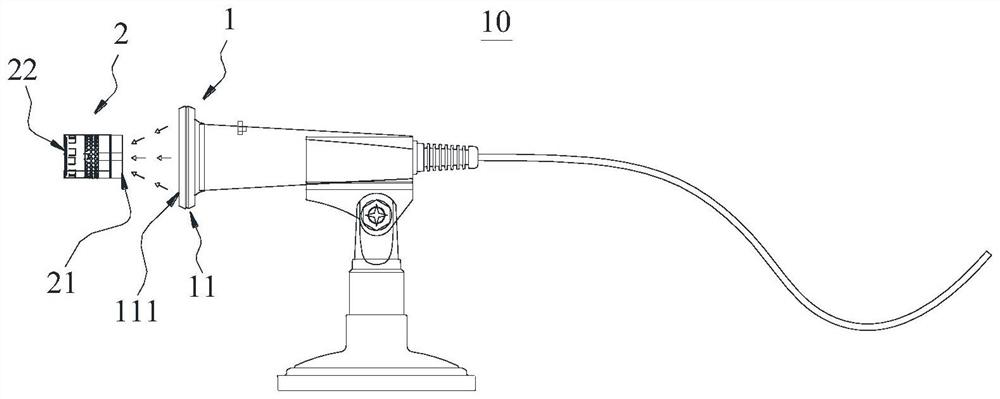
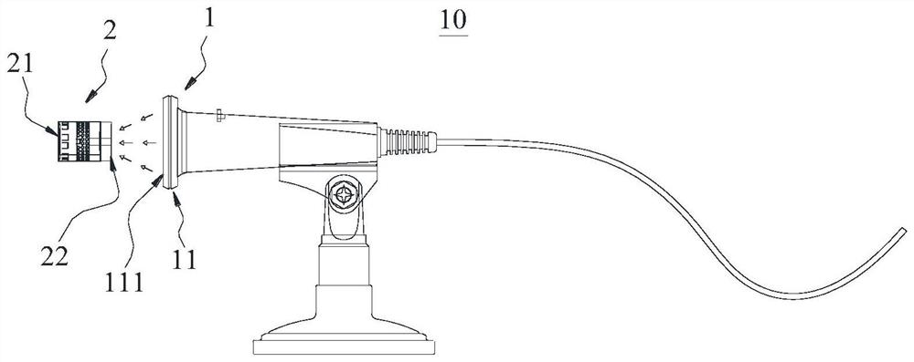
[0053] First, the first side surface 21 is configured to receive sound waves reflected by the reflecting surface 111, and the second side surface 22 is configured to be fully open to receive sound waves, or partially open to receive sound waves in a limited manner;

[0054] Second, the first side surface 21 is configured to receive the sound waves reflected by the reflection surface 111, and the second side surface 22 is configured to be completely closed to isolate the sound waves;

[0055] Third, the second side surface 22 is configured to receive the sound waves reflected by the reflection surface 111, and the first side surface 21 is configured to be fully open to receive the sound waves, or partially open to receive the sound waves in a limited manner;

[0056] Fourth, the second side surface 22 is configured to receive the sound waves reflected by the reflection surface 111 , and the first side surface 22 is configured to be completely closed to isolate the sound waves. ...


PUM


Abstract

According to the pickup structure and the use method thereof, the reflection surface is arranged on the reflection assembly, and the first side surface and the second side surface are arranged on the pickup assembly, so that sound waves incident from a preset direction can be gathered to the side surface, used for receiving the sound waves, on the pickup assembly through the reflection surface; therefore, sound wave pickup at a farther distance in the preset direction can be performed without using a high-sensitivity pickup assembly, and the positive feedback phenomenon is avoided while the effective pickup distance is prolonged; furthermore, the sound entering from other directions cannot be reflected by the reflecting surface, so that the use of a complex circuit and algorithm software is avoided, the directional pickup performance is improved, and meanwhile, the increase of the production and manufacturing cost is avoided.

Description

technical field [0001] The present invention relates to the technical field of sound pickup, and more particularly, to a sound pickup structure and a method for using the same. Background technique [0002] Sound pickup structure, a structure that collects sound, is widely used in various application scenarios such as conferences and squares that need to transmit sound; more specifically, sound pickup structure is generally set in products such as microphones. [0003] However, the existing pickup structures generally have the following shortcomings: [0004] First, the effective sound pickup distance is long, and it is difficult for the sound from the sound source in the intended use direction to be fully collected into the pickup microphone head of the sound pickup structure. The user needs to approach the microphone to a short distance, otherwise, the sound source distance The farther the microphone is, the worse the pickup effect; [0005] Second, but corresponding to ...

Claims


Application Information

Patent Timeline
Patent Type & Authority Applications(China)
IPC IPC(8): H04R1/08
CPCH04R1/083
Inventor 倪奇志
Owner 易科技术(东莞)有限公司
Why Eureka
Try Eureka