
Synchronous pressure welding device

A pressure welding, synchronous gear technology, applied in welding equipment, resistance welding equipment, metal processing equipment, etc., can solve the problems of dimensional deviation, unbalanced welding pressure on both sides of the spring, and the welding device cannot be accurately positioned. Improve the effect of dimensional deviation and welding pressure equalization

Inactive Publication Date: 2022-08-02
成都纽安能杰自动化科技有限公司
View PDF0 Cites 0 Cited by
  • Summary
  • Abstract
  • Description
  • Claims
  • Application Information

AI Technical Summary

Problems solved by technology

[0003] The welding device in the prior art has a certain dimensional deviation for the welding position of the strip spring, and there is also an imbalance in the welding pressure on both sides of the spring. Moreover, due to the narrow space during welding, when the spring is hung, the welding device needs to move along the The movement of the strip direction gives way, and the spring is hung and then moved back for welding. The welding device in the prior art cannot be accurately positioned when moving

Method used


Image

  • Synchronous pressure welding device
  • Synchronous pressure welding device
  • Synchronous pressure welding device

Examples


Embodiment

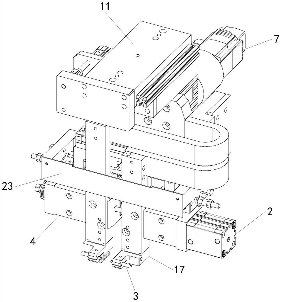
[0037] refer to Figure 1-Figure 6 , figure 1 It is a schematic diagram of the overall structure of the front end of a synchronous pressure welding device in an embodiment of the present invention;

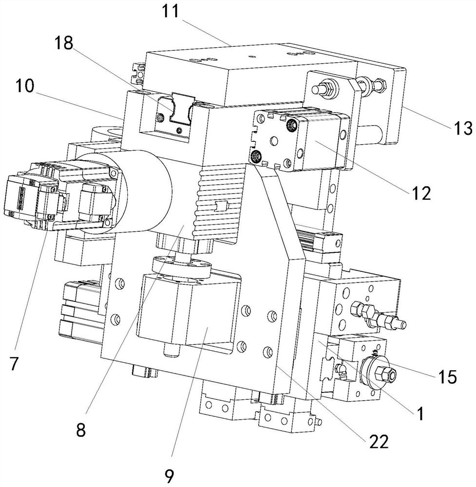
[0038] figure 2 It is a schematic diagram of the overall structure of the rear end of a synchronous pressure welding device in an embodiment of the present invention;

[0039] image 3 It is a side view of a synchronous pressure welding device in an embodiment of the present invention;

[0040] Figure 4 It is a schematic structural diagram of the welding mechanism in the embodiment of the present invention;

[0041] Figure 5 is the front view of the welding mechanism in the embodiment of the present invention;

[0042] Image 6 It is a schematic partial structure diagram of the welding mechanism in the front view in the embodiment of the present invention;

[0043] A synchronous pressure welding device specifically includes: a horizontal moving mechanism, a vertical movi...


PUM


Abstract

The invention provides a synchronous pressure welding device, and relates to the technical field of welding equipment. Comprising a horizontal moving mechanism, a vertical moving mechanism and a welding mechanism, the welding mechanism is connected with the vertical moving mechanism through a first sliding rail, and the vertical moving mechanism is connected with the horizontal moving mechanism through a second sliding rail; the welding mechanism comprises a fixing base, a pressurizing air cylinder, a synchronous gear assembly and two electrodes, the two electrodes are oppositely arranged on two mounting frames, the two mounting frames are connected with two movable sliding blocks correspondingly, the inner side walls of the two movable sliding blocks are connected with the side wall of the fixing base through third sliding rails, and the pressurizing air cylinder is connected with one movable sliding block; the synchromesh gear assembly comprises a synchromesh gear, an upper rack and a lower rack, wherein the upper rack and the lower rack are meshed with the synchromesh gear. The two racks are connected with the two movable sliding blocks through connecting pieces correspondingly. The welding device is balanced in welding pressure, capable of adapting to welding positions of strip springs of different batches, capable of horizontally moving, high in horizontal receding matching degree and accurate in welding positioning.

Description

technical field [0001] The invention relates to the technical field of welding equipment, in particular to a synchronous pressure welding device. Background technique [0002] The strip / spring assembly and welding equipment is used for the manufacture of improved grids for fuel assemblies, and is responsible for the assembly of various types of inner strips and single and double springs, welding of upper and lower solder joints, height detection and defect identification. , wherein the function of the upper welding point welding station is to weld the upper point position of the spring assembled by the previous station (spring / strip assembly) on the strip tooling. The upper solder joint welding station, the spring / strip assembly station and the strip indexing device cooperate here to complete the tooling for the spring to be hooked into the strip window and welded. [0003] The welding device in the prior art has a certain dimensional deviation on the welding position of th...

Claims


Application Information

Patent Timeline
Patent Type & Authority Applications(China)
IPC IPC(8): B23K11/02B23K11/11B23K11/31
CPCB23K11/02B23K11/115B23K11/31Y02E30/30
Inventor 林盾孟令江凌云
Owner 成都纽安能杰自动化科技有限公司
Learn More