Intelligent mold manufacturing auxiliary system and method

An auxiliary system and mold manufacturing technology, applied in the direction of manufacturing tools, metal processing machinery parts, metal processing equipment, etc., can solve the problems of reduced coverage, difficult water flow blocking, etc.

Pending Publication Date: 2022-08-02
林永龙
View PDF0 Cites 0 Cited by
  • Summary
  • Abstract
  • Description
  • Claims
  • Application Information

AI Technical Summary

Problems solved by technology

[0004] In the process of processing, it is inevitable to carry out punching, engraving or cutting. In order to reduce the temperature generated in the process and ensure the smoothness of the processing, water is usually sprayed on the surface of the cast plate, and the water pressure is also very high. Large ones, in the prior art, most of the jets are sprayed at an angle of 45° above the casting plate to reduce the impact force brought by the water flow, but sometimes the casting plate needs to be adjusted in position, such as rotation, which leads to reducing the impact force Even if you can control the position of the nozzle adjustment, the water flow direction of the adjusted nozzle is still sprayed from top to bottom, and the sprayed water will splash around after touching the casting plate, making it difficult for the water tank to keep the water sprayed out. The water flow is blocked, and the sprayed water flow acts on the casting plate in a point-like manner, resulting in reduced coverage

Method used


Image

  • Intelligent mold manufacturing auxiliary system and method
  • Intelligent mold manufacturing auxiliary system and method
  • Intelligent mold manufacturing auxiliary system and method

Examples


no. 1 example

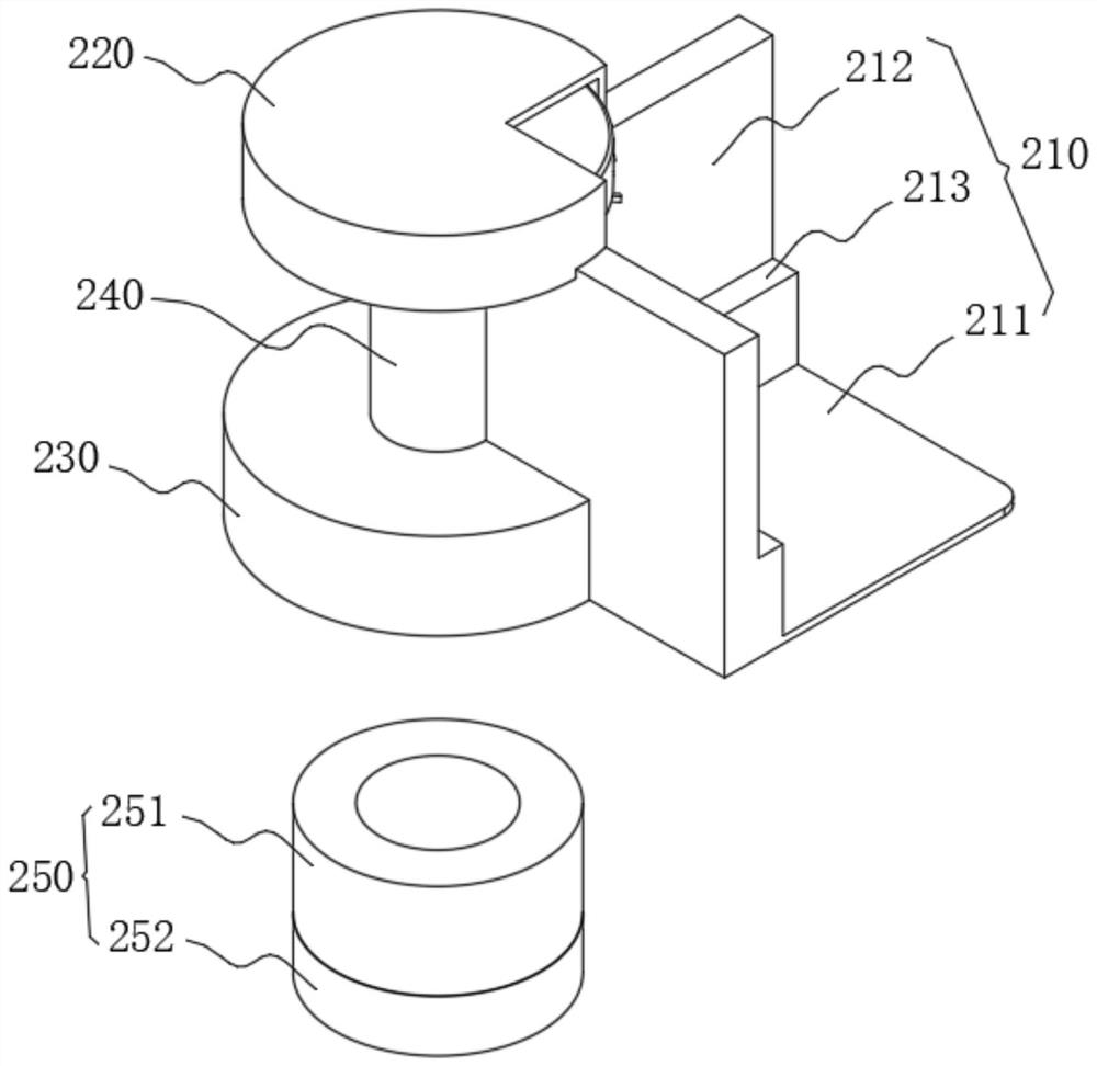
[0054] For the first embodiment, see image 3 As shown, the water flow guiding mechanism 200 includes a support member 210, a water outlet member 220 and a water inlet member 230. The support member 210 includes a side plate 212 in an "L" shape structure, and the side plate 212 is adapted to the casting plate 300 through the "L" shape structure. corner, and a flange 213 is provided on the side where the side plate 212 and the corner of the casting plate 300 are attached to support the casting plate 300. A plug space is formed, which is connected to the corner of the cast plate 300 through the plug space. The bottom of the flange 213 is provided with a bottom plate 211. After the cast plate 300 and the side plate 212 are installed, a water storage space is formed between the bottom plate 211 and the cast plate 300. In this way, the water flow ejected from the water flow output member 120 is blocked by the casting plate 300 and expands around, and then the expanded water flow en...

no. 3 example

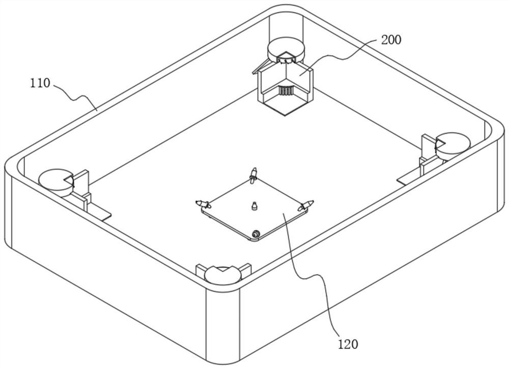
[0063] The third embodiment, this embodiment specifically discloses a water flow output member 120. The water flow output member 120 includes a spray head 122. The spray head 122 is arranged at the bottom of the operating cavity 100A. The bottom of the spray head 122 is provided with a water inlet pipe 1221. The water inlet pipe 1221 passes through the water tank. The bottom wall of 110 is connected with the nozzle 122 , and the water flow connected to the water inlet pipe 1221 is sprayed out through the nozzle 122 .

no. 4 example

[0064] The fourth embodiment, this embodiment discloses another implementation of the water flow output member 120 , please refer to Figure 8 As shown, there are at least five spray heads 122, preferably five, and the water flow output member 120 further includes a square connecting plate 121, and the bottom of the connecting plate 121 is provided with a plurality of pillars 1211, through which the connecting plate 121 is installed on the On the bottom wall of the water tank 110, four of the five spray heads 122 are arranged at the corners of the connection plate 121 and face the water storage cavity 211A, and the remaining one is arranged at the center of the connection plate 121, towards the top, when working , see Figure 9 and Figure 10 As shown in the figure, the water flow from the nozzles 122 at the center is blocked by the casting plate 300 and spreads around, but the water flow into the water storage cavity 211A is limited, so the nozzles 122 at the four corners ar...


PUM


Abstract

The invention relates to the technical field of mold manufacturing, in particular to an intelligent mold manufacturing auxiliary system and method. The auxiliary device comprises a water flow output mechanism and a casting plate, the water flow output mechanism comprises a water tank with an opening in the top, the auxiliary device further comprises a water flow guide mechanism, the casting plate is placed in the operation cavity and supported through the water flow guide mechanism, and a space for water flow output is formed between the bottom of the casting plate and the bottom wall of the water tank. Water flow is output upwards through the bottom, acts on the bottom wall of the casting plate and is diffused all around, then the water flow is sucked by the water flow guiding mechanism and is guided to be horizontally sprayed out of the top of the casting plate, the sprayed water flow covers the top of the casting plate, and therefore the problem that in the punching or carving or cutting process, the water flow is sprayed out from top to bottom to make contact with the casting plate and then splashes all around is solved. In addition, the problem that the coverage range is low due to the fact that spraying acts on the casting plate in a point-shaped mode is solved.

Description

technical field [0001] The invention relates to the technical field of mold manufacturing, in particular, to an intelligent mold manufacturing auxiliary system and method. Background technique [0002] The mold mainly realizes the processing of the shape of the article by changing the physical state of the material to be formed, and under the action of external force, the blank becomes a tool for a part with a specific shape and size. Widely used in blanking, die forging, cold heading, extrusion, powder metallurgy pressing, pressure casting, and compression molding or injection molding of engineering plastics, rubber, ceramics and other products; [0003] In general, the mold making process is as follows: drawing review - material preparation - processing (mold base processing, mold core processing, electrode processing and mold parts processing) - inspection - assembly - flying mold - test mold - production. [0004] Punching, engraving or cutting is inevitable in the proc...

Claims


Application Information

Patent Timeline
IPC IPC(8): B23Q11/00B23Q11/10C23G3/00
CPCB23Q11/10B23Q11/0042C23G3/00
Inventor 林永龙
Owner 林永龙
Why Eureka
Try Eureka