Submersible automatic laying and recovery device

A recovery device and submersible technology, applied in the field of marine engineering, can solve the problems of high cost of deployment operations, poor adaptability, difficulty in completing deployment and recovery by manpower, etc., to meet the needs of repeated deployment and recovery operations, reduce effect of complexity

Active Publication Date: 2022-08-02
广东智能无人系统研究院(南沙)
View PDF14 Cites 0 Cited by
  • Summary
  • Abstract
  • Description
  • Claims
  • Application Information

AI Technical Summary

Problems solved by technology

The deployment and recovery process of submersibles consumes a lot of manpower, material resources and time. The traditional deployment and recovery methods have big problems in terms of work efficiency and operating costs.
Especially for large and medium-sized submersibles, it is difficult to complete deployment and recovery by manpower, and the cost of conventional ship deployment operations is high
[0003] The existing technologies for similar purposes usually use manual operation of the boom to fix the submersible. The adaptability to harsh sea conditions is not strong. The motion response of the ship under the action of waves will have a negative impact on the deployment and recovery of the submersible. Seriously, it may It will cause impact damage to the equipment due to shaking; secondly, the current deployment and recovery method of the submersible that automatically throws the rope into the sea through the rope throwing device is difficult to achieve automatic reset, making it difficult to realize the fully unmanned submersible deployment and recovery operation, so There is an urgent need for an unmanned automatic deployment and recovery equipment and method

Method used


Image

  • Submersible automatic laying and recovery device
  • Submersible automatic laying and recovery device
  • Submersible automatic laying and recovery device

Examples


Embodiment

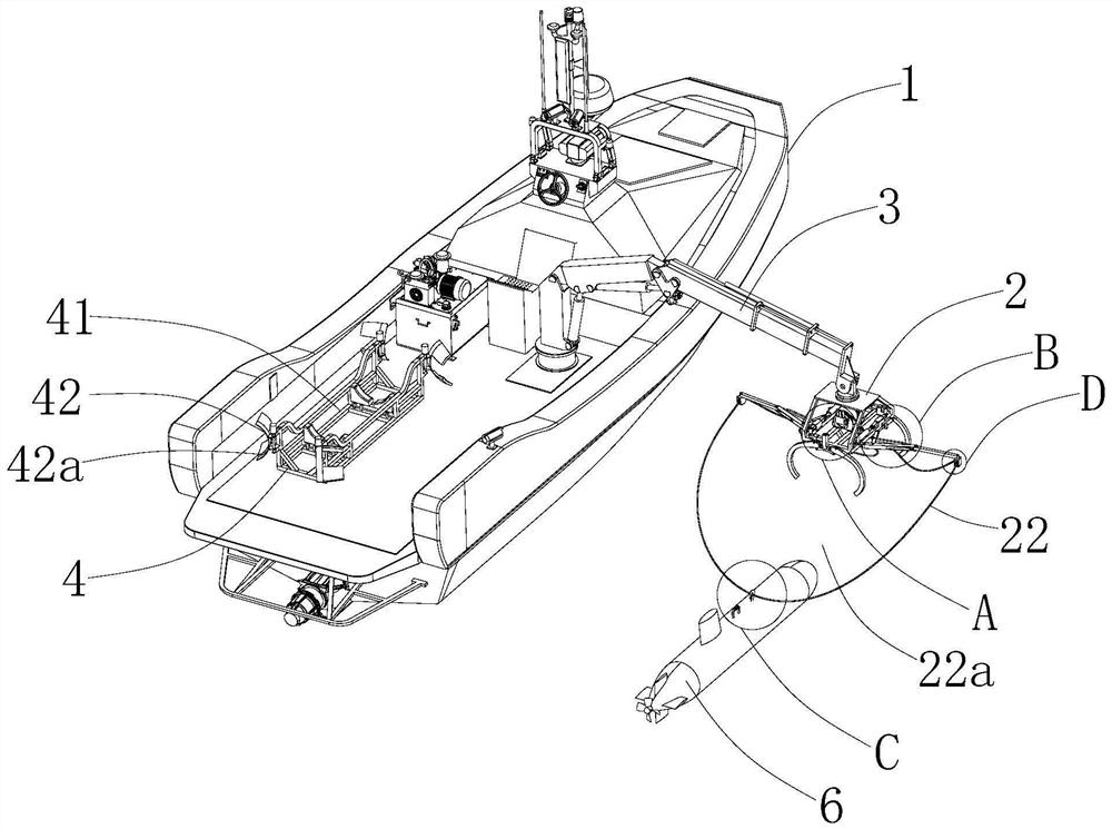
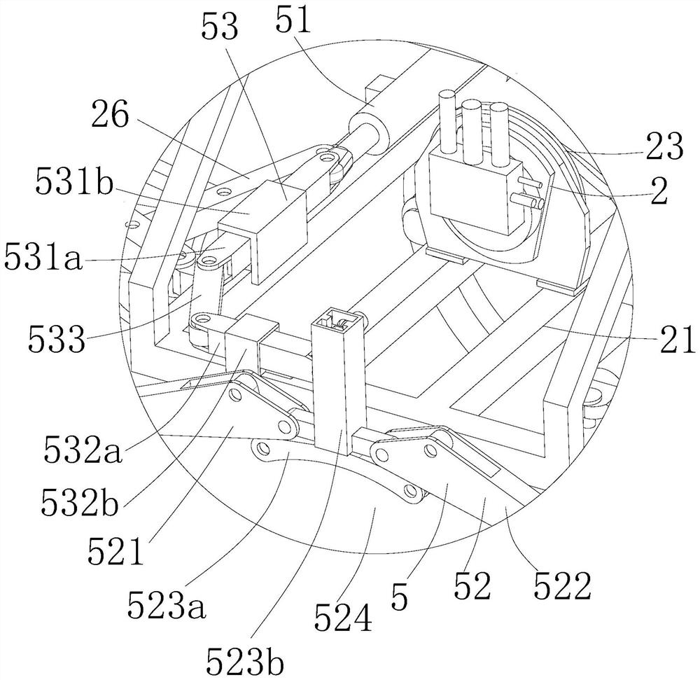
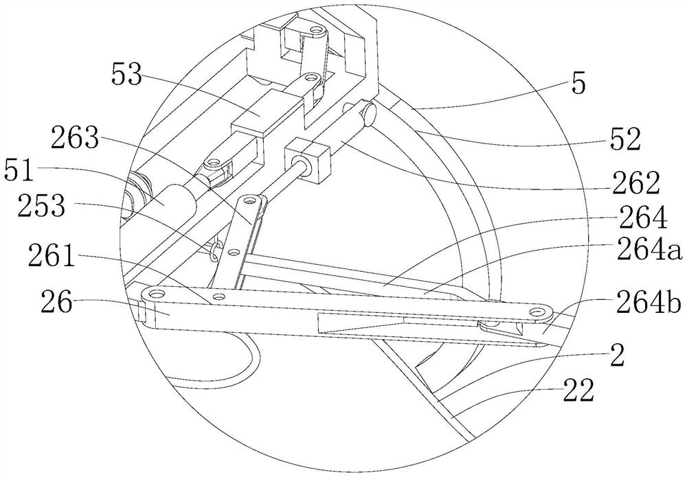
[0073] Example: a submersible automatic deployment and recovery device, such as Figure 1 to Figure 10 As shown, it can be applied to a submersible 6 with a hook 61, which includes: a carrier 1, a pulling and retracting device 2, a hoisting device 3, a bracket 4, a locking assembly 42, and a control system, as follows:

[0074] The carrier 1 is used as a mother ship for submersible operations on water; in this embodiment, the carrier 1 is an unmanned ship, but it is not limited to this, and can also be other marine structures capable of carrying the submersible 6 . This solution can be installed on an unmanned ship, and the carrier 1 as the unmanned ship provides power and control instructions, so as to realize a stable and reliable deployment and recovery operation of the submersible 6 .

[0075] The hoisting device 3 is arranged on the carrier 1, which can hoist or lower the submersible 6, and the pulling and retracting device 2 is arranged on the movable end of the hoisting...


PUM


Abstract

The invention discloses an automatic launching and recovering device for a submersible, relates to the technical field of ocean engineering, and solves the problems that the adaptability to severe sea conditions is not strong and the equipment is possibly impacted and damaged due to shaking because a lifting arm is generally manually operated to fix the submersible, and the key point of the technical scheme is that the automatic launching and recovering device comprises a carrier; the traction winding and unwinding device comprises a traction winding and unwinding frame arranged on the carrier; the folding mechanism is arranged on the traction folding and unfolding frame; one end of the traction cable is connected with the traction retractable frame, the other end of the traction cable is connected with the movable end of the folding mechanism, and the traction cable is provided with a traction area; according to the scheme, a specific implementation mode for realizing the recovery and laying operation of the submersible through the traction recovery and laying device is provided, the device can adapt to the working condition that the submersible is subjected to the recovery operation in the state that the motion response of a carrier is large, and the complexity of the recovery operation can be effectively reduced; and the automatic recovery process of the submersible can also be achieved.

Description

technical field [0001] The invention relates to the technical field of marine engineering, in particular to an automatic deployment and recovery device for submersibles. Background technique [0002] Submersibles are the most commonly used tools for marine resource exploration, marine environment monitoring, marine scientific research, and underwater operations. Before submersibles operate, it is usually necessary to put the submersible into the water through the retractable device on the mother ship. The deployment and recovery process of submersibles consumes a lot of manpower, material resources and time. The traditional deployment and recovery methods have major problems in terms of work efficiency and operating costs. Especially for large and medium-sized submersibles, it is difficult to complete the deployment and recovery by manpower, and the deployment operation cost of conventional ships is high. [0003] The existing technologies for similar purposes usually use m...

Claims


Application Information

Patent Timeline
Patent Type & Authority Applications(China)
IPC IPC(8): B63B27/16B63B27/08
CPCB63B27/16B63B27/08B63B2027/165Y02A20/204
Inventor 薛乃耀杨文林叶作霖
Owner 广东智能无人系统研究院(南沙)
Why Eureka
Try Eureka