Scaffold mounting structure convenient to mount and dismount
A technology for installing structures and scaffolding, which is applied in the connection of scaffolding, building structure support, building structure support, etc. It can solve the problems of complex structure connection, troublesome assembly process, and time-consuming disassembly, so as to simplify the installation structure and facilitate assembly. convenient effect
- Summary
- Abstract
- Description
- Claims
- Application Information
AI Technical Summary
Problems solved by technology
Method used
Image

Examples
Embodiment 1
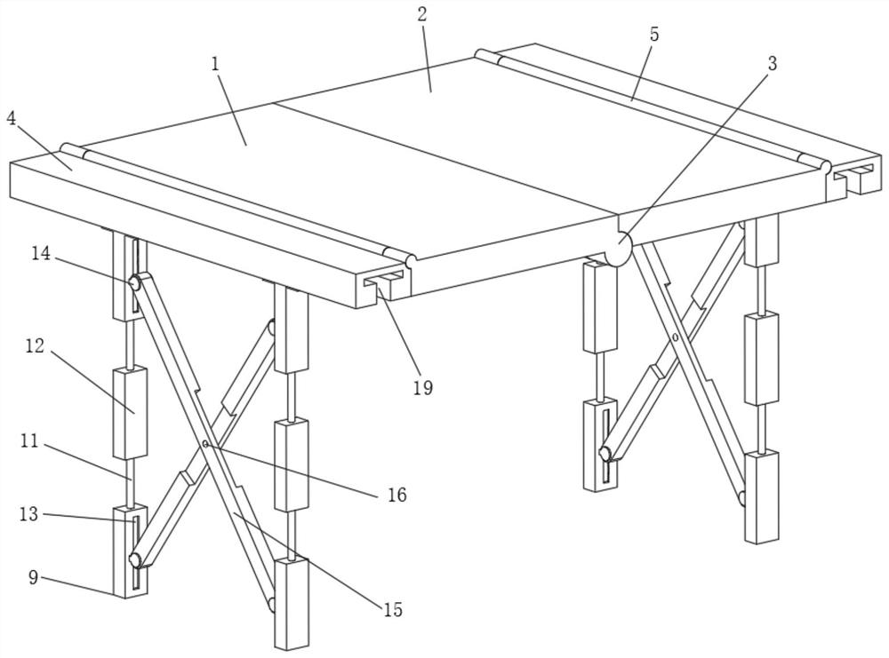
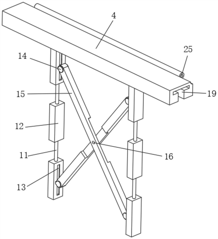
[0032] A scaffolding installation structure that is easy to install and disassemble, the scaffolding installation structure includes a support table, a support assembly 9 and an end plate 4 .
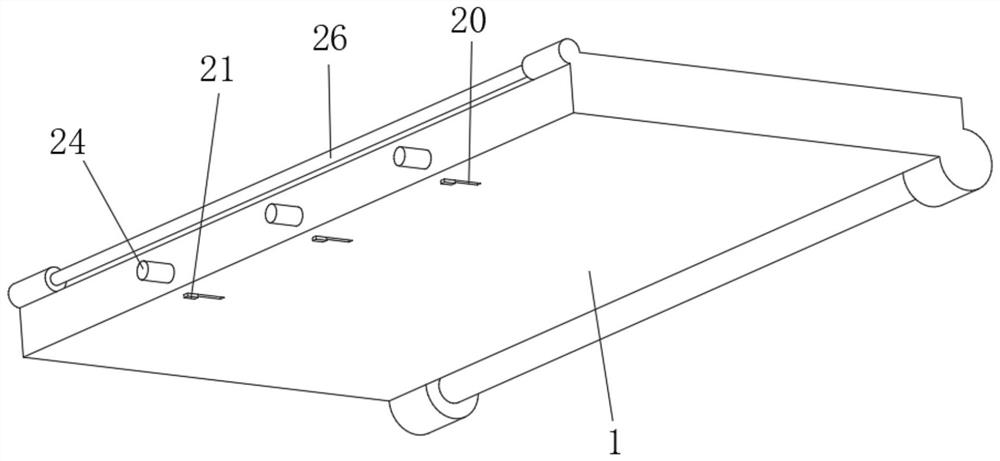
[0033] The support table is composed of a first support plate 1 and a second support plate 2. The first support plate 1 and the second support plate 2 are connected by rotation through a large hinge assembly 3. The first support plate 1 and the second support plate 2 The outer sides are provided with small hinge assemblies 5, the upper end of the end plate 4 is rotated and installed on the outside of the first support plate 1 and the second support plate 2 through the small hinge assembly 5, and the large hinge assembly 3 and the small hinge assembly 5. Both are composed of a sleeve 25 and a rotating shaft 26 , and the sleeve 25 is rotatably sleeved on the rotating shaft 26 .
[0034] By arranging the large hinge assembly 3 and the small hinge assembly 5, the folded connection between t...
Embodiment 2
[0043] On the basis of Embodiment 1, in order to realize convenient transportation during transportation, the present application also has a roller 10 provided at the lower end of the support assembly 9 , and the transportation efficiency is improved by providing the roller 10 .
Embodiment 3
[0045] On the basis of Embodiment 2, in order to improve the structural strength between the support assemblies 9, the present application also has two sets of linearly distributed telescopic beams between the adjacent pair of support assemblies 9, and the two ends of the telescopic beams are sleeved. Connected to the connecting rod 11, the telescopic beam is composed of a telescopic rod 7 and a beam tube 6. The telescopic rod 7 is inserted into a pair of left and right symmetrical beam tubes 6, and the telescopic rod 7 and the beam tube 6 are connected by fastening screws 8. Fixed connection.
[0046] By arranging telescopic beams for telescopic connection, it is possible to connect and support the laterally adjacent support assemblies 9, thereby improving the lateral support strength.
PUM
 Abstract
Description
Claims
Application Information