Pump body powerful self-suction structure

A powerful, self-priming technology, applied in the direction of pumps, pump components, driving pumps, etc., can solve the problems of only 2.5-3.5 meters, occupying a large space on site, and long self-priming time, achieving high self-priming height, saving space, The effect of short self-priming time

Pending Publication Date: 2022-08-02
阳光泵业(天津)有限公司
View PDF0 Cites 0 Cited by
  • Summary
  • Abstract
  • Description
  • Claims
  • Application Information

AI Technical Summary

Problems solved by technology

[0002] Self-priming pumps are widely used in petrochemical, urban environmental protection, construction, fire protection, chemical industry, pharmaceuticals, dyes, printing and dyeing, brewing, electric power, electric ferry, papermaking, industrial and mining flushing, equipment cooling and other fields, accounting for more than 10% of the total pump consumption. At present, domestic self-priming pumps generally have the problem of long self-priming time and low self-priming height during use, and the self-priming height is generally only 2.5-3.5 meters
In the face of the above technical problems, two methods are usually used to solve them: one is to add a sufficiently large volume siphon tank before the inlet of the centrifugal pump, but the cost is high and it takes up a lot of space on site; the other is to install a unique siphon tank at the inlet of the centrifugal pump Suction device, but the cost is higher, and the failure rate is also higher during use

Method used


Image

  • Pump body powerful self-suction structure
  • Pump body powerful self-suction structure
  • Pump body powerful self-suction structure

Examples


Embodiment Construction

[0018] The present invention will be further described below with reference to specific embodiments and accompanying drawings to help understand the content of the present invention.

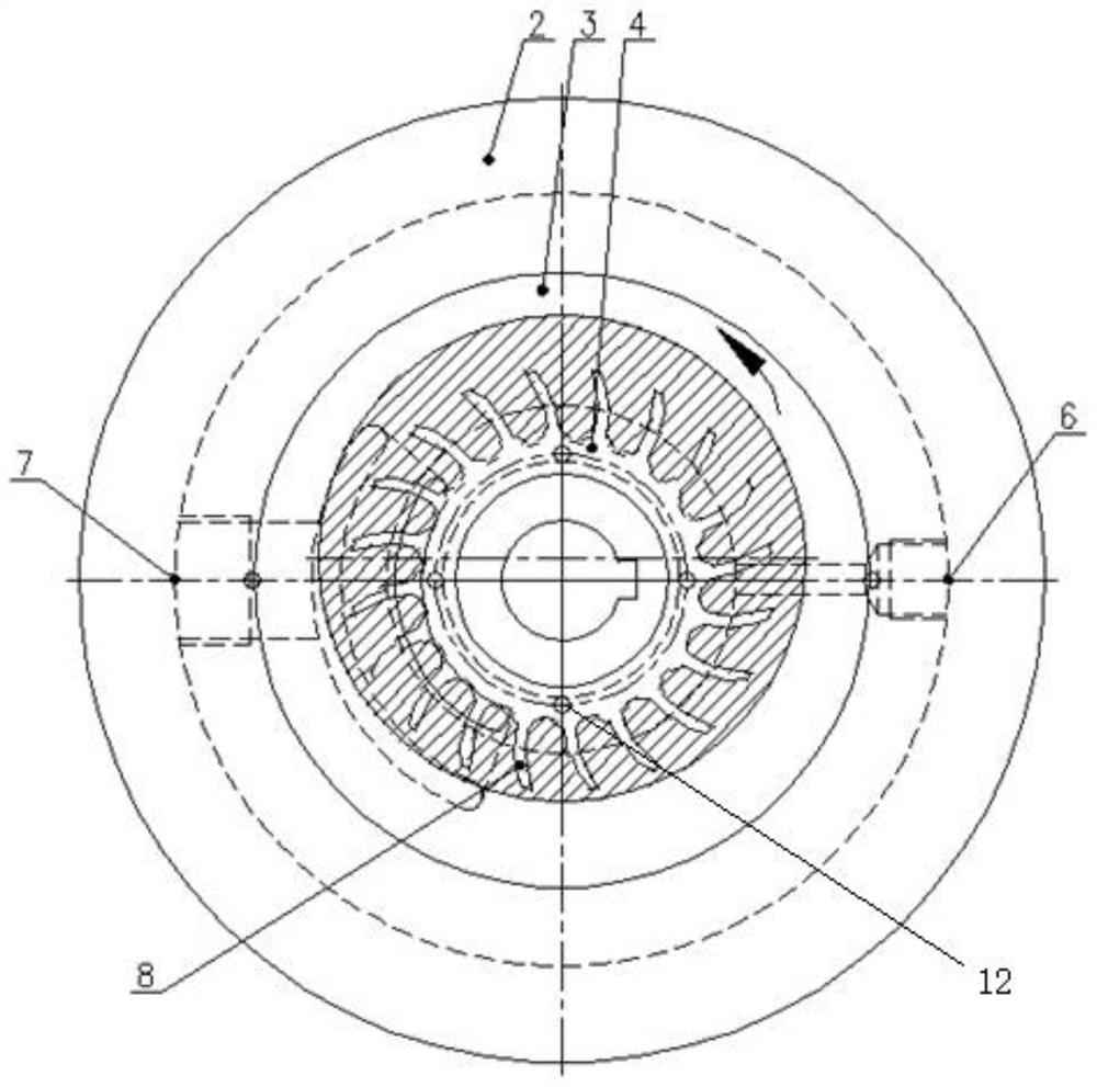
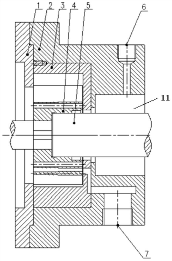
[0019] like Figure 1-2 shown, respectively, are a front view and a side cross-sectional view of a strong self-priming structure of a pump body provided by the present invention. The strong self-priming structure of the pump body includes a pump cover 1, an eccentric chamber seat 2, an eccentric chamber 3, an impeller 4 and a pump shaft 5. The impeller 4 is installed between the pump cover 1 and the eccentric chamber 3, and its front and rear clearance is 0.3- 0.35mm, the inner hole of the impeller 4 and the pump shaft 5 are clearance fit. Preferably, the inner hole of the impeller 4 is installed on the pump shaft 5 according to the H7 / h6 small clearance fit.

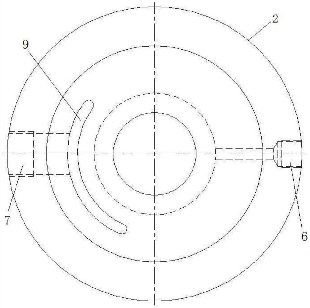
[0020] like Figure 4 As shown, it is a front view of the eccentric chamber of a strong self-priming structure of a pump body provide...


PUM


Abstract

The invention discloses a pump body powerful self-suction structure which comprises a pump cover, an eccentric chamber base, an eccentric chamber, an impeller and a pump shaft, the impeller is installed between the pump cover and the eccentric chamber, the front-back gap of the impeller is 0.3-0.35 mm, an inner hole of the impeller is in clearance fit with the pump shaft, the eccentric chamber is upwards eccentric by 5-6 mm, a first crescent groove is formed in the back face of the eccentric chamber, and the eccentric chamber base is arranged outside the eccentric chamber in a sleeving mode. A second crescent groove communicated with the first crescent groove is formed in the eccentric chamber base, the second crescent groove is communicated with an exhaust port in the eccentric chamber base, the eccentric chamber base is fixedly connected with the pump cover, working fluid is contained in the eccentric chamber, an air inlet is formed in the side, opposite to the exhaust port, of the eccentric chamber base, the air inlet is communicated with the pump cavity, and the number of blades of the impeller is more than 20. The self-suction impeller is simple in structure, ingenious in design, space-saving, low in cost, capable of quickly and automatically sucking liquid after exhausting, short in self-suction time, high in self-suction height, wide in application prospect and beneficial to popularization and application.

Description

technical field [0001] The invention relates to the technical field of self-priming pumps, in particular to a strong self-priming structure of a pump body. Background technique [0002] Self-priming pumps are widely used in petrochemical, urban environmental protection, construction, fire protection, chemical industry, pharmaceuticals, dyes, printing and dyeing, brewing, electric power, electric ferry, papermaking, industrial and mining washing, equipment cooling and other fields, accounting for more than 10% of the total pump consumption. At present, domestic self-priming pumps generally have the problems of long self-priming time and low self-priming height during use, and the self-priming height is generally only 2.5-3.5 meters. In the face of the above technical problems, two methods are usually used to solve them: one is to add a siphon tank with a large enough volume before the inlet of the centrifugal pump, but the cost is high and the site space is occupied; The suc...

Claims


Application Information

Patent Timeline
Patent Type & Authority Applications(China)
IPC IPC(8): F04D9/02F04D29/00F04D29/24F04D29/42F04D29/44
CPCF04D9/02F04D29/007F04D29/24F04D29/426F04D29/445
Inventor 王云平丁垣利任卫东徐少芬
Owner 阳光泵业(天津)有限公司
Why Eureka
Try Eureka