
Display panel and display device

A technology for display panels and display areas, applied in semiconductor devices, electrical components, circuits, etc., and can solve problems such as inability to cure, light-transmitting glue blocking

Pending Publication Date: 2022-08-02
KUNSHAN GO VISIONOX OPTO ELECTRONICS CO LTD
View PDF0 Cites 0 Cited by
  • Summary
  • Abstract
  • Description
  • Claims
  • Application Information

AI Technical Summary

Problems solved by technology

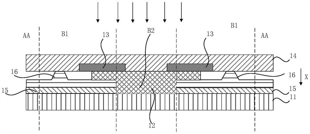
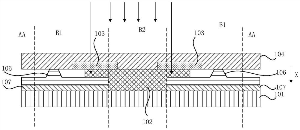
However, the shielding layer and the light-transmitting layer overlap. Therefore, when the light-transmitting layer is cured and light is used to irradiate the light-transmitting adhesive, there is a problem that part of the light-transmitting adhesive is blocked and cannot be cured.

Method used


Image

  • Display panel and display device
  • Display panel and display device
  • Display panel and display device

Examples


Embodiment Construction

[0043] In order to make those skilled in the art better understand the solutions of the present invention, the technical solutions in the embodiments of the present invention will be clearly and completely described below with reference to the accompanying drawings in the embodiments of the present invention. Obviously, the described embodiments are only Embodiments are part of the present invention, but not all embodiments. Based on the embodiments of the present invention, all other embodiments obtained by persons of ordinary skill in the art without creative efforts shall fall within the protection scope of the present invention.

[0044] It should be noted that the terms "first", "second" and the like in the description and claims of the present invention and the above drawings are used to distinguish similar objects, and are not necessarily used to describe a specific sequence or sequence. It is to be understood that the data so used may be interchanged under appropriate ...


PUM

PropertyMeasurementUnit
refractive indexaaaaaaaaaa

Abstract

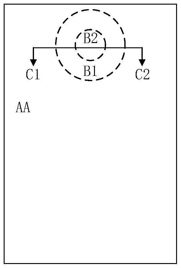
The invention discloses a display panel and a display device. The display panel comprises a display area, a frame area and a light-transmitting area. The display area is arranged around the frame area, and the frame area is arranged around the light-transmitting area; the display panel further comprises a substrate; the light-transmitting layer is arranged on the substrate and located in the light-transmitting area and at least part of the frame area; the shielding layer is arranged on the side, away from the substrate, of the light transmitting layer, and at least part of the shielding layer is located in the frame area; the orthographic projection of the shielding layer on the substrate is partially overlapped with the orthographic projection of the light-transmitting layer on the substrate; wherein the shielding layer is used for shielding light of which the wavelength is within a visible spectral range and is used for transmitting light of which the wavelength is within an infrared spectral range to the light transmitting layer; or the frame area further comprises a light adjusting structure, and the light adjusting structure is used for adjusting the light to the light transmitting layer. According to the technical scheme of the embodiment of the invention, the light-transmitting layer is completely cured.

Description

technical field [0001] The present invention relates to the field of display technology, and in particular, to a display panel and a display device. Background technique [0002] With the rapid development of display technology, the requirements for light transmission in the camera area of ​​the display panel are getting higher and higher. [0003] The camera area may be provided with blind holes to improve the light transmittance of the camera area. When blind holes are set in the camera area, light-transmitting glue can be filled in the blind holes, which can reduce the reflection of light at the interface between the substrate and the gas at the blind holes, and further increase the light transmittance in the camera area. At the same time, a shielding layer may be provided under the encapsulation layer in the frame area around the blind hole, so as to reduce the light interference of the external light and the light emitted from the display area of ​​the display panel to...

Claims


Application Information

Patent Timeline
Patent Type & Authority Applications(China)
IPC IPC(8): H01L27/32
CPCH10K59/50
Inventor 邱岳李文星王子豪
Owner KUNSHAN GO VISIONOX OPTO ELECTRONICS CO LTD
Learn More