
High-voltage electric appliance cabinet for electrical automation control

A technology of electrical automation and high-voltage electrical appliances, which is applied in the direction of electrical components, climate change adaptation, chemical instruments and methods, etc., can solve the problems that the heat of electrical cabinets cannot be discharged in time, the volume of high-voltage electrical cabinets is large, and the operation of electronic components is broken. Dust-proof effect, improved moisture-proof effect, and improved safety effect

Pending Publication Date: 2022-08-02
扬州菲德电气有限公司
View PDF0 Cites 0 Cited by
  • Summary
  • Abstract
  • Description
  • Claims
  • Application Information

AI Technical Summary

Problems solved by technology

[0003] There are the following problems: Most of the high-voltage electrical cabinets are mainly metal-enclosed structures. Although the protective effect of the high-voltage electrical cabinets can be greatly improved, it also causes the heat generated inside the electrical cabinets to be unable to be discharged in time, so there are certain safety hazards. Serious Sometimes it will lead to bad situations such as open circuit in the operation of electronic components, and the common high-voltage electrical cabinets are relatively large and difficult to move, which seriously hinders the daily cleaning work

Method used


Image

  • High-voltage electric appliance cabinet for electrical automation control
  • High-voltage electric appliance cabinet for electrical automation control
  • High-voltage electric appliance cabinet for electrical automation control

Examples


Embodiment Construction

[0037] The technical solutions in the embodiments of the present invention will be clearly and completely described below with reference to the accompanying drawings in the embodiments of the present invention. Obviously, the described embodiments are only a part of the embodiments of the present invention, but not all of the embodiments. Based on the embodiments of the present invention, all other embodiments obtained by those of ordinary skill in the art without creative efforts shall fall within the protection scope of the present invention.

[0038] In the description of the present invention, it should be noted that the terms "center", "upper", "lower", "left", "right", "vertical", "horizontal", "inner", "outer", etc. The indicated orientation or positional relationship is based on the orientation or positional relationship shown in the accompanying drawings, which is only for the convenience of describing the present invention and simplifying the description, rather than ...


PUM


Abstract

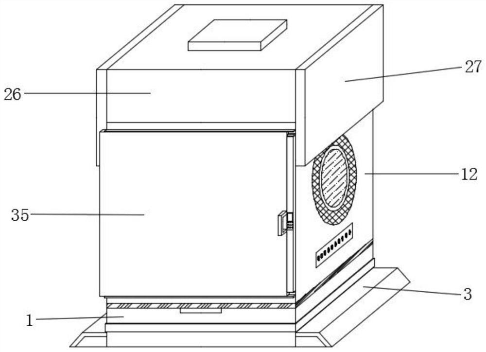
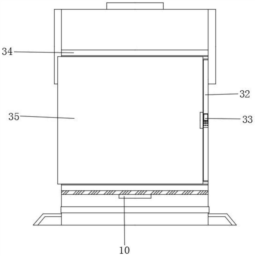
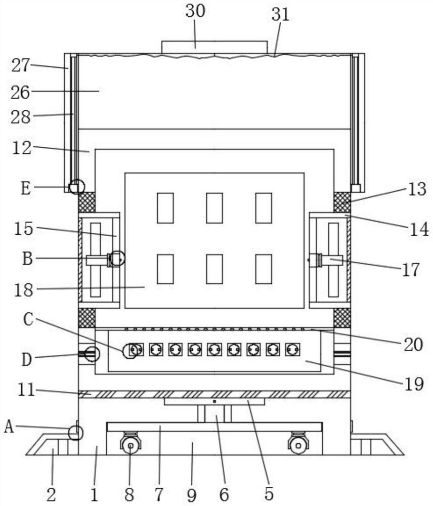
The invention relates to the technical field of electric appliance cabinets, in particular to a high-voltage electric appliance cabinet for electrical automation control, which comprises a base, mounting plates connected to the bottom ends of the outer walls of the two sides of the base, rubber pads connected to the tops of the mounting plates, a fluorescent pasting ring connected to the center of the outer wall of the base, and a power box connected to the inner wall of the center of the top of the base. Lifting columns are connected to the two ends of the bottom of the power box correspondingly, supporting plates are connected to the bottoms of the lifting columns correspondingly, and steering rollers are connected to the two ends of the bottom of each supporting plate correspondingly. By arranging the fan shaft, the most basic heat dissipation effect can be achieved, the temperature in the equipment can be detected at any time by arranging the temperature sensing control element, and when the temperature in the equipment reaches a certain limit, the fan shaft can rotate immediately to rapidly discharge heat from the heat dissipation frame.

Description

technical field [0001] The invention relates to the technical field of electrical cabinets, in particular to a high-voltage electrical cabinet for electrical automation control. Background technique [0002] High-voltage electrical cabinets refer to the functions of on-off, control or protection in power generation, transmission, distribution, power conversion and consumption of power systems, mainly including high-voltage circuit breakers, high-voltage isolation switches and grounding switches, high-voltage load switches, high-voltage automatic Reclosing and sectionalizers, high-voltage operating mechanisms, high-voltage explosion-proof power distribution devices and high-voltage switch cabinets are several categories. The high-voltage switch manufacturing industry is an important part of the power transmission and transformation equipment manufacturing industry and occupies a very important position in the entire power industry. . [0003] There are the following problems...

Claims


Application Information

Patent Timeline
Patent Type & Authority Applications(China)
IPC IPC(8): H02B1/52H02B1/56H02B1/28H02B1/30H02B1/50B08B1/00B65H54/54
CPCH02B1/52H02B1/565H02B1/28H02B1/30H02B1/50B65H54/54B65H2701/34B08B1/12B08B1/30Y02A30/14
Inventor 冯兆清
Owner 扬州菲德电气有限公司
Learn More