Extra-high voltage cable stress cone jacking device

A technology of jacking device and stress cone, applied in cable installation device, cable installation, electrical components, etc., can solve the problems of reduced stress cone effect, cable joint failure, easy to absorb dust, etc., to increase friction and facilitate cleaning. Dust, fixed and stable effect

Pending Publication Date: 2022-08-02
党亚军
View PDF0 Cites 0 Cited by
  • Summary
  • Abstract
  • Description
  • Claims
  • Application Information

AI Technical Summary

Problems solved by technology

[0004] 1. The fixation of the existing UHV cable stress cone tightening device is not firm enough. During the long-term operation of the UHV cable, the stress cone may become loose and eccentric, resulting in a decrease in the effect of the stress cone and failure of the cable joint;
[0005] 2. The existing UHV cable stress cone tightening device is inconvenient for cleaning dust, because there is static electricity around the UHV cable, it is easier to absorb dust, and the dust is inconvenient to handle

Method used


Image

  • Extra-high voltage cable stress cone jacking device
  • Extra-high voltage cable stress cone jacking device
  • Extra-high voltage cable stress cone jacking device

Examples


Embodiment 1

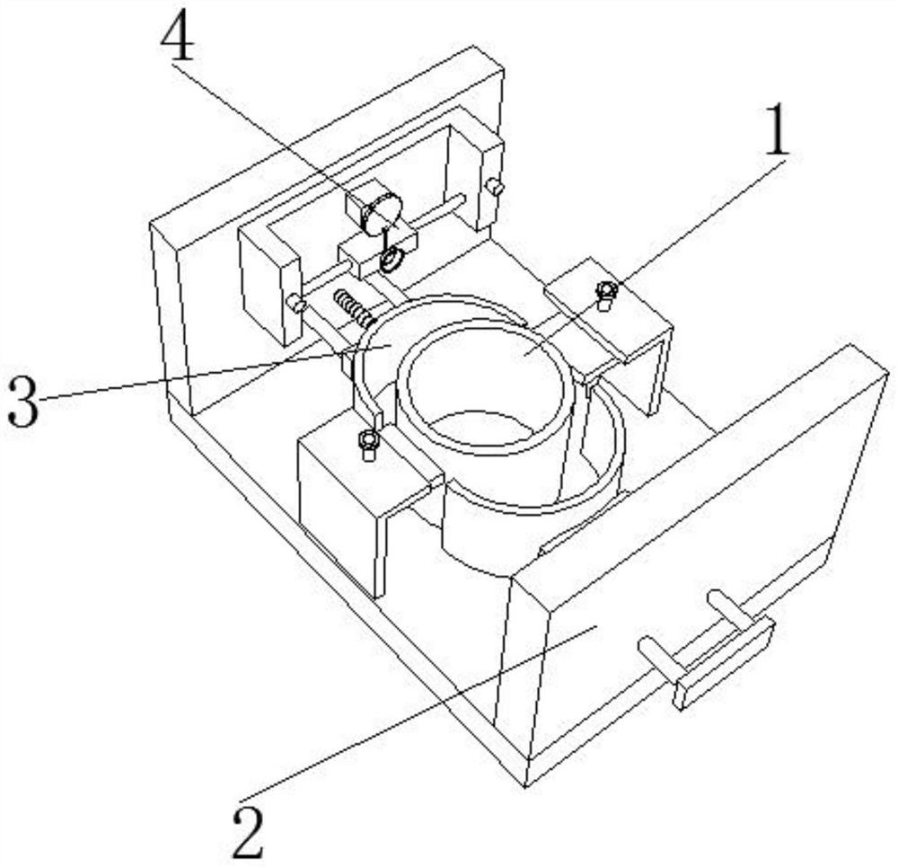
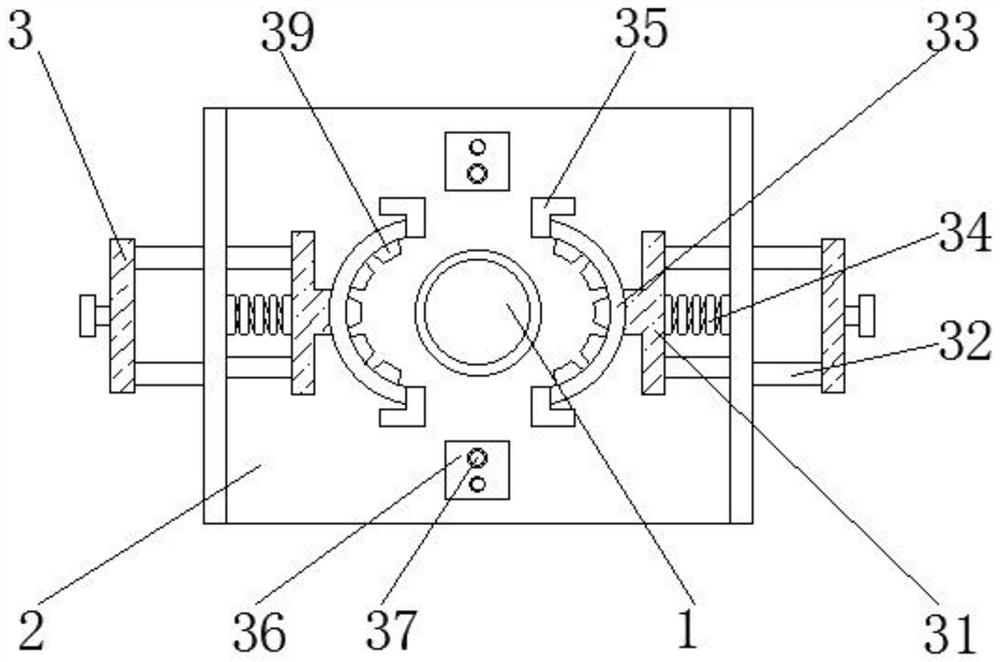
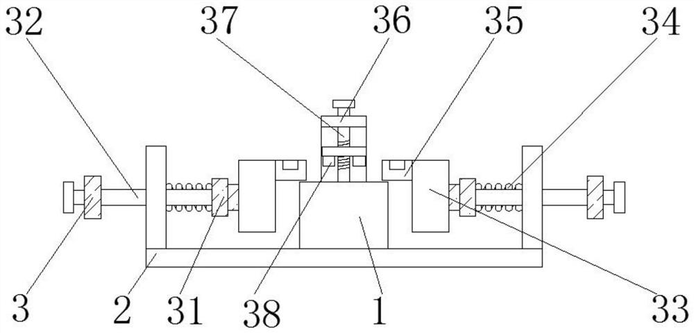
[0030] like Figure 1-6 As shown in the figure, the present invention provides an ultra-high voltage cable stress cone pressing device, comprising a stress cone body 1, a base 2 is arranged below the stress cone body 1, and a clamping mechanism 3 is arranged above the base 2 of the stress cone body 1 , one side of the clamping mechanism 3 is provided with a dust suction mechanism 4, the clamping mechanism 3 includes a connecting block 31, a sliding rod 32 and a clamping bar 33, the connecting block 31 is arranged on both sides of the stress cone body 1, and the sliding rod 32 is fixed Installed on the outer wall of one side of the connection block 31, the outer wall of the sliding rod 32 is movably connected with the inner wall of the base 2, the clamping bar 33 is fixedly installed on the outer wall of the connection block 31, and the dust suction mechanism 4 includes a motor 41 and a moving block 42. And the vacuum cleaner 43, the motor 41 is arranged above the base 2, the m...

Embodiment 2

[0033] like Figure 1-6 As shown, on the basis of Embodiment 1, the present invention provides a technical solution: preferably, the rebound assembly 39 includes an arc-shaped block 391, an elastic hemisphere 392 and a fan-shaped connecting block 393, and the arc-shaped block 391 is fixedly installed in the clip On the inner wall of the tightening bar 33, the elastic hemisphere 392 is fixedly installed on one side outer wall of the arc block 391, the fan-shaped connecting block 393 is fixedly installed on one side outer wall of the elastic hemisphere 392, and the one side outer wall of the arc block 391 is fixedly installed There is an elastic connecting column 394, one end of the elastic connecting column 394 is fixedly connected with one side outer wall of the fan-shaped connecting block 393, a fan-shaped rubber frame 395 is fixedly installed on one side outer wall of the fan-shaped connecting block 393, and the inner wall of the fan-shaped rubber frame 395 is fixedly installed...

Embodiment 3

[0036] like Figure 1-6 As shown, on the basis of Embodiment 1, the present invention provides a technical solution: preferably, a support rod is fixedly installed on one side outer wall of the base 2, and a door-shaped block is movably installed on the outer wall of the support rod. One side inner wall of the motor 41 is fixedly connected with the one side outer wall of the motor 41, a turntable 44 is fixedly installed on the output shaft of the motor 41, a hinge rod is movably installed on one side outer wall of the turntable 44, and the bottom end of the hinge rod is connected to the top of the moving block 42. Fixed connection, the inner wall of the door-shaped block is fixedly installed with a round rod 45, the outer wall of the round rod is movably connected with the inner wall of the moving block 42, a support block is fixedly installed on the outer wall of one side of the base 2, and the inner wall of the support block is movably installed with a clamping rod 46. ​​One...


PUM


Abstract

The invention discloses an extra-high-voltage cable stress cone jacking device, and relates to the technical field of high-voltage cable stress cones, the extra-high-voltage cable stress cone jacking device comprises a stress cone body, a base is arranged below the stress cone body, a clamping mechanism is arranged above the base of the stress cone body, and a dust collection mechanism is arranged on one side of the clamping mechanism. The clamping mechanism comprises connecting blocks, sliding rods and clamping strips, the connecting blocks are arranged on the two sides of the stress cone body, the sliding rods are fixedly installed on the outer walls of one sides of the connecting blocks, and the outer walls of the sliding rods are movably connected with the inner wall of the base. Under the interaction of a pulling plate, a connecting block, a sliding rod, clamping strips, a first spring, an L-shaped plate, an L-shaped block, a threaded rod, a clamping block and a springback assembly, a stress cone body is fixed through the springback assembly on the clamping strips, meanwhile, a rotary knob is rotated to drive the threaded rod to rotate, the threaded rod drives the clamping block on the sliding plate to be clamped into a clamping groove, the two clamping strips are locked, and therefore the stress cone body is fixed. And the fixing is convenient.

Description

technical field [0001] The invention relates to the technical field of high-voltage cable stress cones, in particular to an ultra-high-voltage cable stress cone top-tightening device. Background technique [0002] High-voltage cable is a kind of power cable. It refers to the power cable used to transmit between 1kv and 1000kv. A radially distributed electric field is formed between the core and the metal sheath, that is to say, the electric field of a normal cable has only the electric field power line from the core to the grounding metal sheath along the radius, and there is no electric field electric field power line in the axial direction of the core wire, and the electric field distribution is uniform. , When the cable head is used to connect the two sections of the cable, the original electric field distribution of the cable is changed due to the stripping of the insulation and shielding layers, which will generate a tangential electric field (power line along the axis ...

Claims


Application Information

Patent Timeline
Patent Type & Authority Applications(China)
IPC IPC(8): H02G1/00B08B5/04
CPCH02G1/00B08B5/04
Inventor 党亚军
Owner 党亚军
Why Eureka
Try Eureka