
Electrified mounting and dismounting device for magnetic bird repeller

A technology for dismantling devices and bird repellents, which is applied to the installation of cables, overhead installations, electrical components, etc., can solve the problems of poor practicability, poor stability, and inability to install bird repellents, etc., to achieve strong practicability and stability Effect

Pending Publication Date: 2022-08-02
STATE GRID SHANDONG ELECTRIC POWER
View PDF0 Cites 0 Cited by
  • Summary
  • Abstract
  • Description
  • Claims
  • Application Information

AI Technical Summary

Problems solved by technology

[0003] Aiming at the deficiencies of the prior art, the present invention provides a live installation and disassembly device of a magnetic bird repellent, which has two-point installation, can be adjusted to adapt to the distance of the high-voltage line, automatically adapts to the thickness of the high-voltage line, and the magnetic installation is stable and fast. The advantages of installation and disassembly solve the problem of the poor stability of the single-point installation of the bird repellent proposed in the background technology and the fact that a section of high-voltage line must be powered off before it can be operated during the installation process, which has large limitations and poor practicability, and different types of high-voltage lines There are differences in thickness, and it is very easy to appear that the bird repellent cannot be installed during the installation process, and when the bird repellent is damaged after installation, it is very easy to be difficult to disassemble and take a lot of time during the disassembly process

Method used


Image

  • Electrified mounting and dismounting device for magnetic bird repeller
  • Electrified mounting and dismounting device for magnetic bird repeller
  • Electrified mounting and dismounting device for magnetic bird repeller

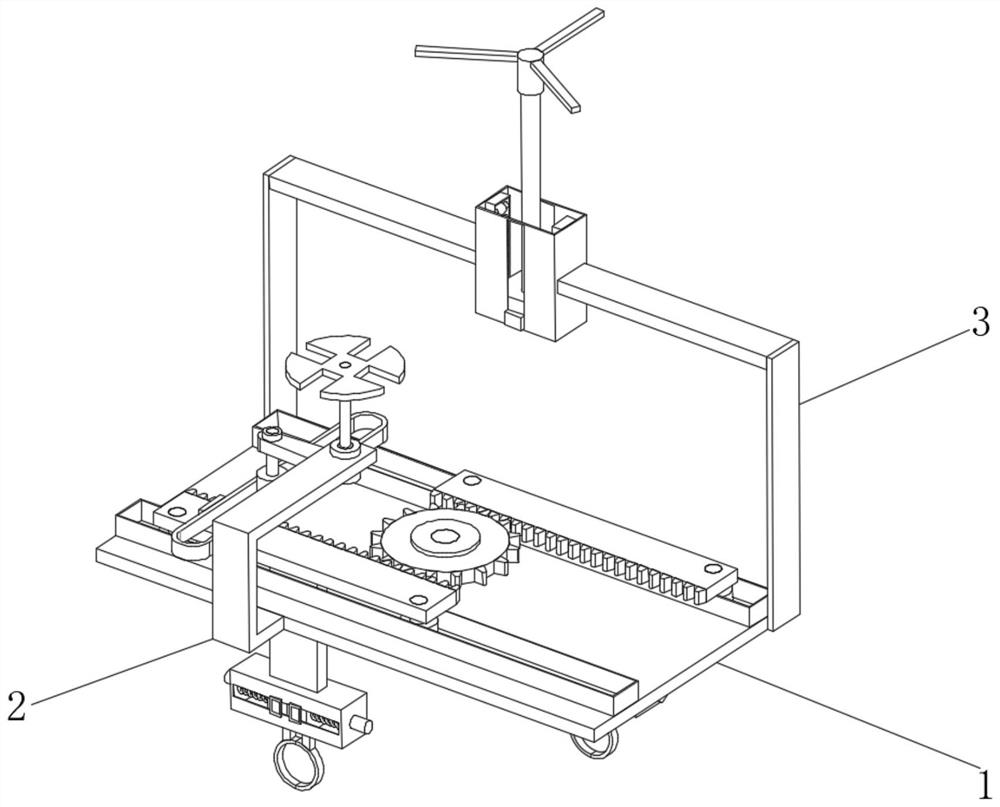
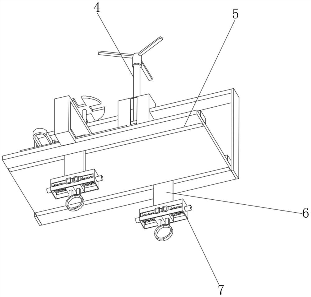
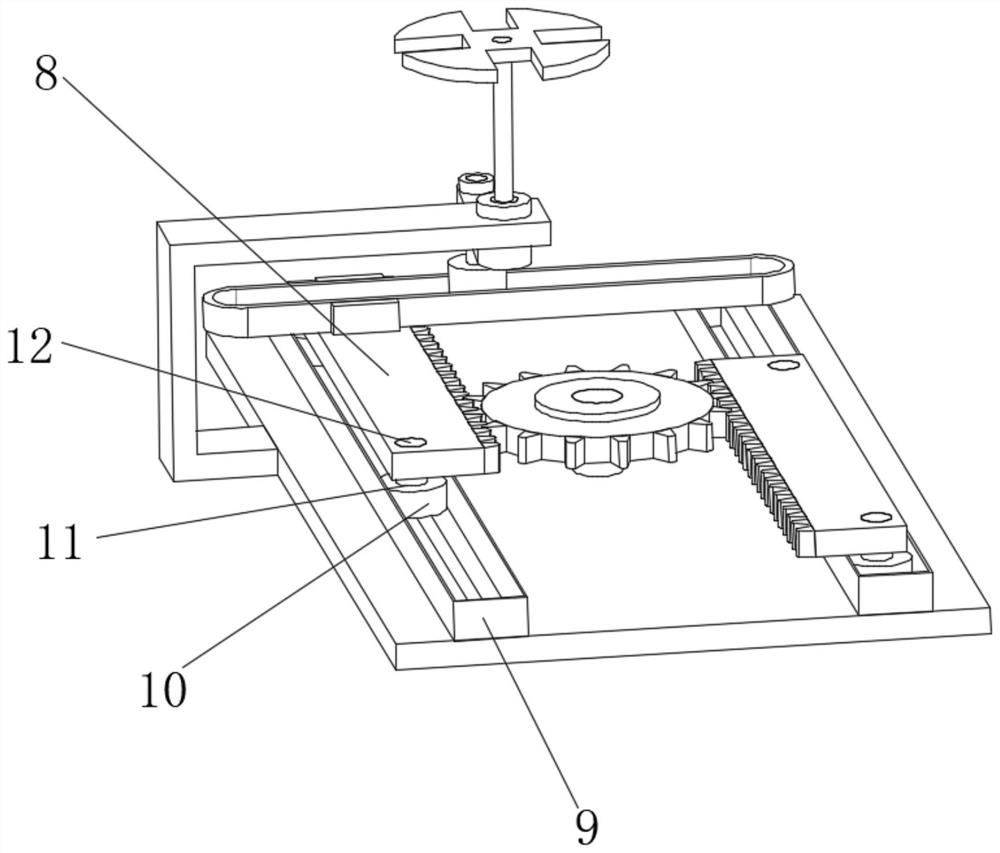
Examples


Embodiment Construction

[0023] The technical solutions in the embodiments of the present invention will be clearly and completely described below with reference to the accompanying drawings in the embodiments of the present invention. Obviously, the described embodiments are only a part of the embodiments of the present invention, but not all of the embodiments. Based on the embodiments of the present invention, all other embodiments obtained by those of ordinary skill in the art without creative efforts shall fall within the protection scope of the present invention.

[0024] see Figure 1-6 , a magnetic bird repellent live installation and disassembly device, comprising an installation base plate 1, the top of the installation base plate 1 is fixedly installed with two fixed casings 9, and the interior of the two fixed casings 9 are provided with two rotating circles Block 10, the tops of the two rotating circular blocks 10 are provided with a rotating groove 11, the interior of the rotating groove...


PUM


Abstract

The invention relates to the technical field of power equipment, and discloses a magnetic type bird repeller live-line mounting and dismounting device which comprises a mounting substrate, and two fixing sleeve shells are fixedly mounted at the top of the mounting substrate. According to the electrified mounting and dismounting device for the magnetic bird repeller, a connecting handle is used for controlling an extension connecting convex block fixedly clamped to the surface of an internal fixing shaft to rotate, and a push rod connected with the extension connecting convex block reciprocates in an annular sleeve shell fixedly mounted on the side face of a rack top fixing block in the rotating process; two rotating round blocks movably connected with the bottom of a rotating column fixedly clamped with the racks move in the fixed sleeve shell, and in the moving process, the two racks are meshed with an auxiliary gear, the auxiliary gear serves as a center linkage piece to rotate on the surface of the fixed column, and therefore the two racks are in a synchronous moving state; the stability of two-point installation is high, the installation distance can be synchronously adjusted, and the practicability is higher.

Description

technical field [0001] The invention relates to the technical field of electrical equipment, in particular to a live installation and removal device of a magnetic suction bird repellent. Background technique [0002] The bird repellent is to drive away birds and prevent the birds from standing on the high-voltage wire and causing electrocution to cause a short circuit in the line. The existing bird repellent is installed on a separate line of the high-voltage line, and the stability of single-point installation is relatively high. In addition, a section of high-voltage line must be powered off during the installation process to operate, which has large limitations and poor practicability. At the same time, the thickness of high-voltage lines of different models is different. It is very easy for the bird repeller to fail to be installed during the installation process. When the installed bird repellent is damaged, it is easy to be difficult to disassemble and the disassembly ...

Claims


Application Information

Patent Timeline
Patent Type & Authority Applications(China)
IPC IPC(8): H02G7/00A01M29/06
CPCH02G7/00A01M29/06
Inventor 王振环张述杰刘大伟曹元敬王涛王洪涛朱宇威赵向国刘龙江崔勇丁慧慧
Owner STATE GRID SHANDONG ELECTRIC POWER
Learn More