Method for ensuring time synchronization of in-vehicle ethernet networks

An in-vehicle network, time synchronization technology, applied in the field of communication networks, to achieve the effect of improving quality, saving test costs, cost and reliability improvement

Pending Publication Date: 2022-08-02
CONTINENTAL AUTOMOTIVE TECH GMBH
View PDF1 Cites 0 Cited by
  • Summary
  • Abstract
  • Description
  • Claims
  • Application Information

AI Technical Summary

Problems solved by technology

This may be used to prevent or at least interrupt safe and correct operation of

Method used


Image

  • Method for ensuring time synchronization of in-vehicle ethernet networks
  • Method for ensuring time synchronization of in-vehicle ethernet networks
  • Method for ensuring time synchronization of in-vehicle ethernet networks

Examples


Embodiment Construction

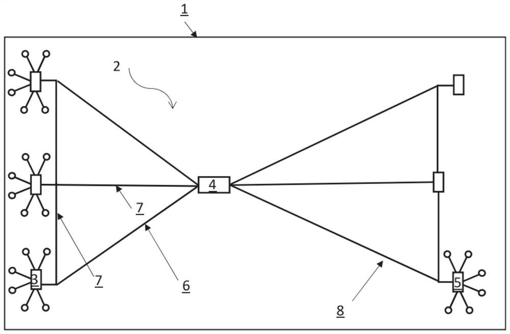
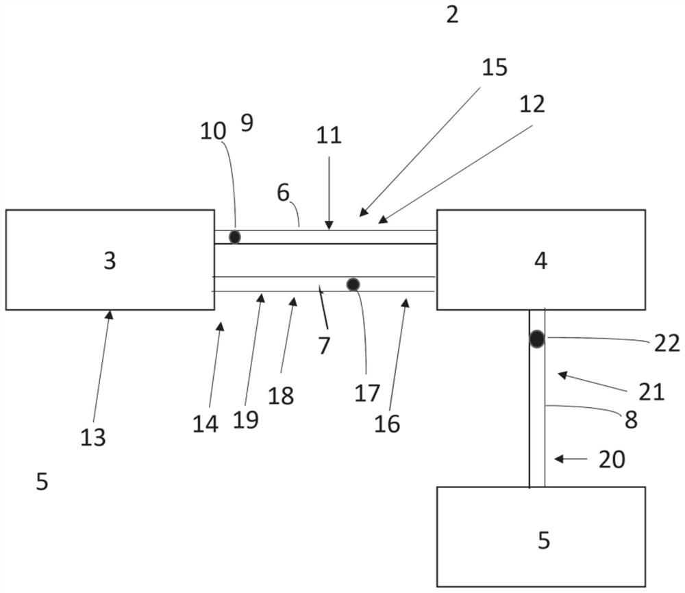
[0085] figure 1 A plan view of the motor vehicle 1 is shown. The motor vehicle 1 has an Ethernet vehicle network 2 . According to an exemplary embodiment, the Ethernet vehicle network 2 in turn has a plurality of control units 3 , 4 , 5 , which may also be referred to as control devices or control devices. In this case, the control units are connected to each other by connection paths. Due to the existing topology of the Ethernet vehicle network 2 in the exemplary embodiment, there are multiple parallel communication paths between the control units. For example, the connection paths may be formed from different media types or materials.

[0086] For example, as the number of Ethernet variants increases, dynamic changes in connection speed will also be used. This means that for example the speed can be changed at runtime. For example, a 10Gbit / s connection path can be changed to 100Mbit / s, thereby saving energy. Since this is a dynamic function, it can happen that, for ex...


PUM


Abstract

The invention relates to a method for ensuring time synchronization of an on-board Ethernet network (2) of a motor vehicle (1), in which the following steps are carried out:-determining a propagation time (9) of a first signal (10) on a first connection path (6) between a first control unit (3) of the on-board Ethernet network (2) and a second control unit (4) of the on-board Ethernet network (2); -determining a maximum velocity (11) of the first connection path (6) on the basis of the propagation time (9); and-determining a type (12) of the transmission medium of the first connection path (6) on the basis of the maximum velocity (11), an entropy source being formed by determining the propagation time (9) of the first signal (10) and determining the maximum velocity (11) of the first connection path and determining the type (12) of the transmission medium of the first connection path (6), at least one dynamic key (28) of the connection path (6) is determined from the entropy source, the at least one dynamic key being used to encrypt a time synchronization message of the connection path (6).

Description

technical field [0001] The present invention relates to a communication network comprising network devices synchronized with each other. technical background [0002] Automotive manufacturers (OEMs) and Tier 1 suppliers to the automotive industry are preparing for next-generation architectures for vehicle controllers or electronic control equipment / control unit ECUs. One development is the so-called "zone-oriented architecture", in which the control devices are grouped into zones such as the right front door zone. The difference from previous architectures is that the controller is located at a specific physical or spatial location to best capture data from the sensors positioned there. Thus, for example, a control unit that collects data from sensors of the right front door can be positioned in the area of ​​the right front door. [0003] Localizing or distributing software execution of features and applications to other controllers and processors is also contemplated. S...

Claims


Application Information

Patent Timeline
Patent Type & Authority Applications(China)
IPC IPC(8): H04L9/40H04L43/0852H04L47/283H04J3/06
CPCH04J3/0667H04L63/0428H04L43/0858H04L47/283H04Q2213/1336H04L63/1408H04L63/067H04L2463/121H04J3/0682H04L67/12
Inventor H·齐内尔
Owner CONTINENTAL AUTOMOTIVE TECH GMBH
Why Eureka
Try Eureka