Removable and wearable appliance and manufacturing method thereof

A manufacturing method and technology of aligners, which are applied in the field of orthodontics, can solve the problems of difficult cleaning and easy fracture of orthodontic appliances, and achieve the effect of large gap, reducing the burden of oral cleaning, and not easy to break

Pending Publication Date: 2022-08-05
GUANGZHOU RITON BIOMATERIAL
View PDF2 Cites 5 Cited by
  • Summary
  • Abstract
  • Description
  • Claims
  • Application Information

AI Technical Summary

Problems solved by technology

[0007] In order to overcome the deficiencies in the prior art, one of the purposes of the present invention is to provide a removable appliance, and the second object is to provide a manufacturing method for the removable appliance; it can solve the problem of existing orthodontics The problem that the device is easy to break and difficult to clean

Method used


Image

  • Removable and wearable appliance and manufacturing method thereof
  • Removable and wearable appliance and manufacturing method thereof
  • Removable and wearable appliance and manufacturing method thereof

Examples


Embodiment 1

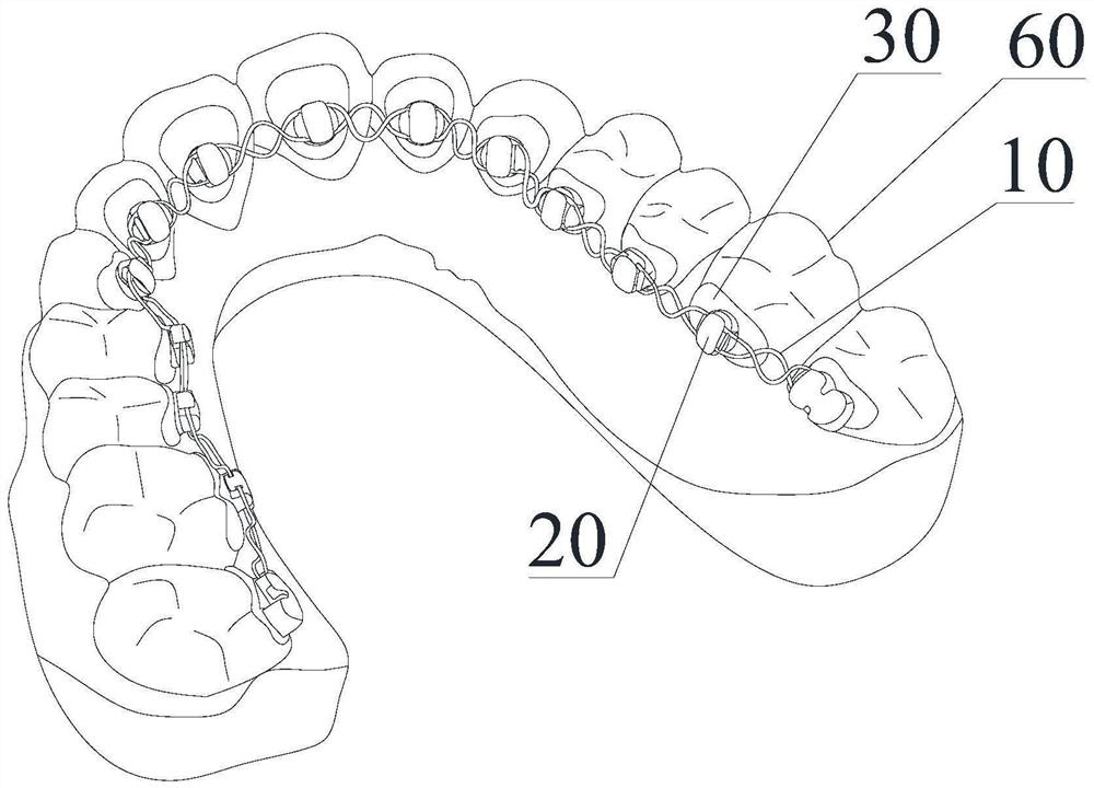
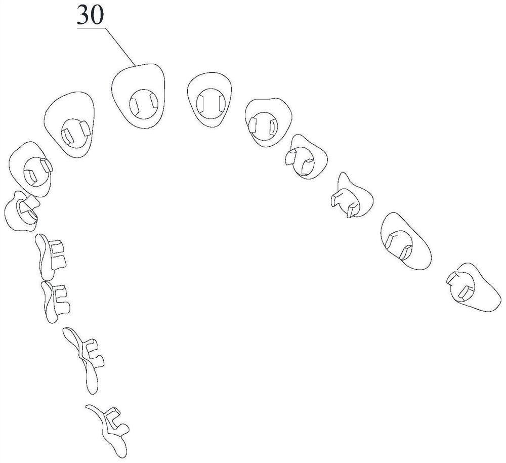
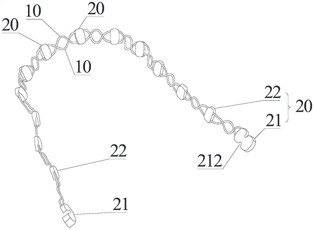
[0069] Example 1: refer to Figure 4-Figure 7 , a lock groove structure 321 is respectively provided on the jaw side and gingival side of the card slot 32; the lock block 20 is fixedly connected with two correction wires 10, that is, in the form of double wires, and the two correction wires 10 are respectively buckled and fixed on Inside the two lock groove structures 321 . When installing the correction wires 10, the two correction wires 10 are snapped into the two locking grooves in parallel to achieve assembly and fixation, and this embodiment has high connection stability.

Embodiment 2

[0070] Embodiment 2: refer to Figure 8-Figure 11 , a lock groove structure 321 is provided on the jaw side or gingival side of the card slot 32, that is, a lock groove is provided on one side, and a groove structure 322 and an insertion groove 324 are provided on the opposite side; the lock block 20 is fixedly connected with a The two correction wires 10 are also in the form of double wires. One end of the lock block 20 is provided with a latch portion 23; In the slot structure 322 , the pin portion 23 is inserted into the insertion slot 324 . The advantage of this embodiment is that it cannot be opened by force in the direction of the lock groove, and can only be opened from the direction of the groove side.

Embodiment 3

[0071] Example 3: Refer to Figure 12-Figure 15 , a lock groove structure 321 is provided on the jaw side and gingival side of the clamping groove 32, and a accommodating groove 323 is also provided between the two lock groove structures 321; , namely the three-wire structure; wherein, the two correcting wires 10 on the two outer sides are respectively fastened and fixed in the two locking groove structures 321 , and the one correcting wire 10 on the middle inner side is placed in the accommodating groove 323 . Compared with the double-wire structure, the three-wire structure can provide more sufficient orthodontic force, and the locking grooves on both sides can also provide a stable connection.


PUM


Abstract

The invention discloses a removable and wearable appliance and a manufacturing method thereof. The removable and wearable appliance comprises an orthodontic wire, a locking block and a bracket, the correction wire is provided with a plurality of curved structures for releasing correction force; at least two correction wires are fixedly connected to each locking block, a plurality of locking blocks are fixed to each correction wire in the length direction of the correction wire, and the number of the locking blocks corresponds to that of the brackets; the bracket comprises a bottom plate and a clamping groove; the at least one correcting wire is detachably connected to the clamping groove, and the locking block is accommodated in the clamping groove. According to the removable and wearable appliance provided by the invention, the orthodontic wires are more difficult to break, and the control effect on tooth torque and axial inclination is better; a plurality of wound orthodontic wires can provide more sufficient orthodontic force; the cleaning is easier, and the daily oral cleaning burden of the patient is reduced.

Description

technical field [0001] The invention relates to the field of orthodontics, in particular to a removable appliance and a manufacturing method of the removable appliance. Background technique [0002] At present, the commonly used devices for correcting malformed dentition include fixed appliances and movable appliances. [0003] Fixed braces are usually composed of brackets and orthodontic arch wires. Mass-produced brackets are usually manufactured by milling, wire cutting, stamping, powder metallurgy and other processes. Custom-made brackets usually use 3D printing resin models, and then lose wax Manufactured by the casting process, the arch wire is usually produced by the die drawing process. During correction, the brackets are fixed on the tooth surface, and the deformed teeth are moved by the force between the groove and the correction arch wire to achieve the purpose of correction. The fixed correction technology has experienced more than one hundred years of developmen...

Claims


Application Information

Patent Timeline
Patent Type & Authority Applications(China)
IPC IPC(8): A61C7/28A61C7/00B33Y10/00B33Y70/00B33Y80/00
CPCA61C7/28A61C7/002B33Y10/00B33Y70/00B33Y80/00
Inventor 李祖安赖奕潮王红卫严淼宁谢卓
Owner GUANGZHOU RITON BIOMATERIAL
Why Eureka
Try Eureka