Blade punching forming device of thin cutter

A thin cutter and blade technology, applied in the field of thin cutter blade punching and forming devices, can solve the problems of reduced work efficiency, unqualified blades, broken metal sheets, etc., so as to improve production efficiency, improve pass rate, and avoid breakage. Effect

Pending Publication Date: 2022-08-05
广东奕源塑胶有限公司
View PDF0 Cites 0 Cited by
  • Summary
  • Abstract
  • Description
  • Claims
  • Application Information

AI Technical Summary

Problems solved by technology

[0002]The stamping machine is a very common equipment in the production workshop. The blade is a strip-shaped metal sheet before stamping. After being stamped by the stamping machine, the metal sheet is stamped and formed. However, in the existing technology, manual hand-held blades are used for stamping and placement. This method has a greater risk and is likely to cause safety accidents. At the same time, the manual method greatly reduces work efficiency and cannot achieve continuous stamping.
Or the inaccurate placement of the metal sheet may easily cause the blade punched out of the metal sheet to be unqualified, thereby reducing the product qualification rate, and most of the punching machines are stamped and formed at one time, because the metal sheet is easily plastically deformed due to strong pressure, causing the metal sheet to break.

Method used


Image

  • Blade punching forming device of thin cutter
  • Blade punching forming device of thin cutter
  • Blade punching forming device of thin cutter

Examples


Embodiment Construction

[0031] In order to make the purpose, technical solutions and advantages of the present invention more clear, the following will be further described in detail with the attachment.

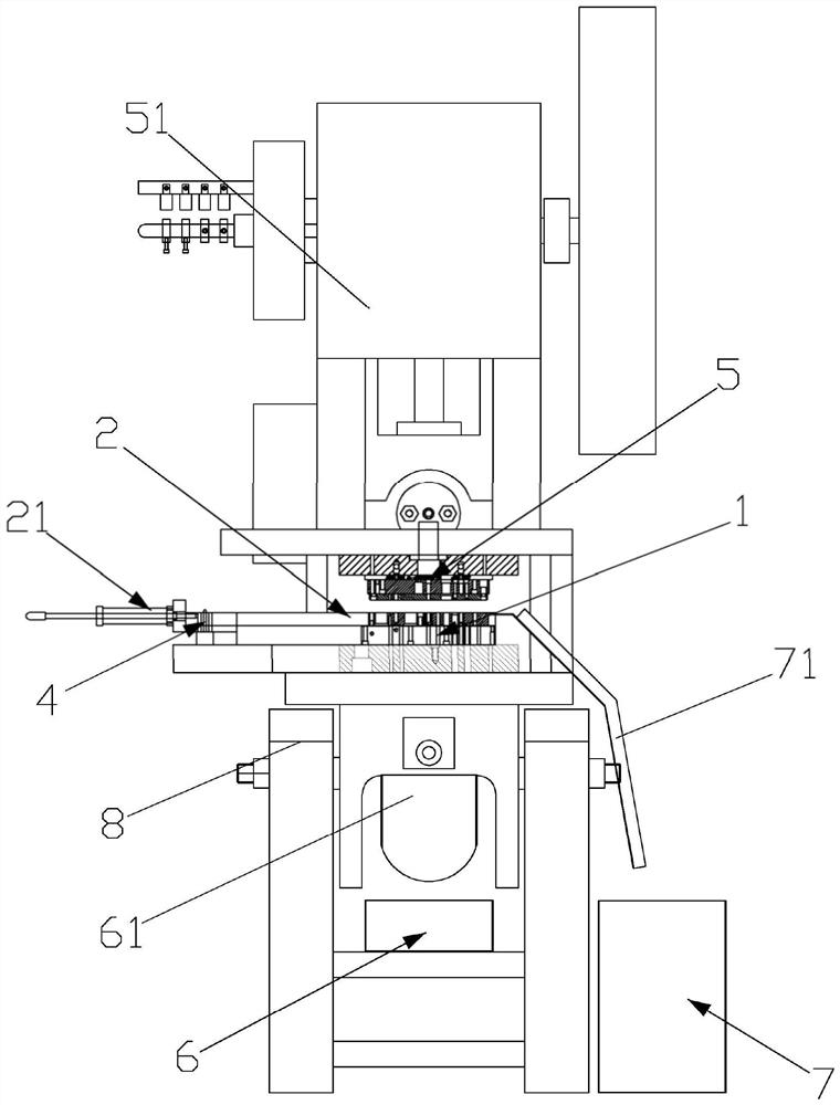
[0032] Reference figure 1 所示,一种薄切割器刀片冲切成型装置,包括模具底座1、滑座2、一对吸嘴3、若干定位块4、冲压模具5、接料盒6、废料盒7、机架8. Base.

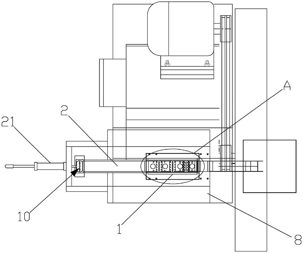
[0033] Reference figure 1 As well as figure 2 Show, mold base 1 is set on the rack 8, the rack 8 rotation is set on the base, the middle part of the mold base 1 has a slider 11, the slide 2 sliding is set on the slide 11 of the mold base 1, the rack is set, and the rack is set. 8 The fixed installation is a sliding driver 21. The example of this embodiment is preferably a cylinder, and its telescopic end is fixed with the slide 2.

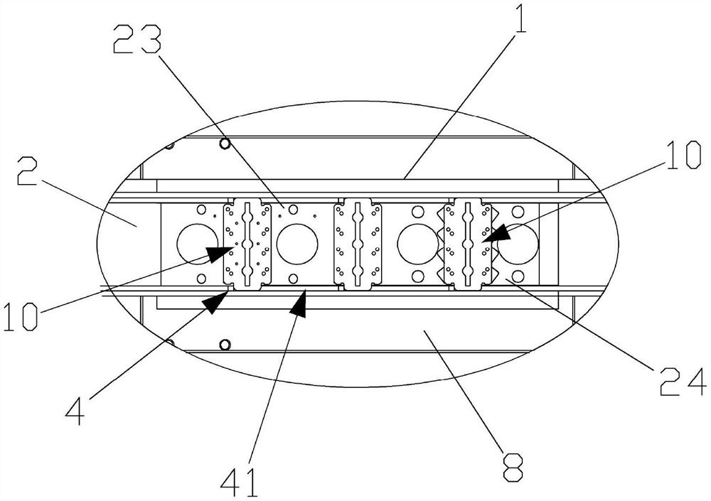
[0034] Reference figure 2 As well as Figure 5 As well as Image 6 It is shown that the suction 3 can be lined at the end of the slide 2, and the bottom of the slide 2 has a feed driver. The example of this embodiment is preferred to use the cylinder. 2 The leader has a opening s...


PUM


Abstract

The invention discloses a thin cutter blade punching forming device which comprises a die base, a sliding seat, a pair of suction nozzles, a plurality of positioning blocks, a stamping die and a material receiving box, a sliding groove is formed in the middle of the die base, the sliding seat is arranged on the sliding groove of the die base in a sliding mode, and the sliding seat is driven by a sliding driving device to horizontally move along the sliding groove. The suction nozzle is arranged at the head end of the sliding seat in a liftable mode and used for sucking a metal sheet and placing the metal sheet on the sliding seat, gaps are formed between the inner side face of the sliding groove and the two sides of the sliding seat respectively, and the multiple positioning blocks are arranged in the gaps in a liftable and spaced mode and used for limiting movement of the metal sheet. The punching die is used for punching the metal sheets on the sliding base, a guide groove is formed in the sliding base in an up-down penetrating mode, the blade is formed under punching of the punching die and pushed into the guide groove, and the formed blade is guided into the receiving box through the guide groove. The device is simple in structure and high in automation degree, and equidistant conveying and automatic punch forming of the blades are achieved.

Description

Technical field [0001] The invention involves the technical field of blade molding equipment, and it specially involves a thin cutter blades flushing molding device. Background technique [0002] The stamping machine is a very common equipment for the production workshop. Before the blade is not stamped, it is a strip -shaped metal piece. After stamping through the stamping machine, the metal sheet is stamped and forming. There are greater risks in this way, which is easy to cause safety accidents. At the same time, the manual method greatly reduces the efficiency of work and cannot achieve continuous stamping. Or inaccurate metal slices are not accurate, which can easily lead to unqualified metal pieces of stamping, thereby reducing the product qualification rate, and most of the punching machines are stamped at one time. Due to the strong application of the metal piece, it is easy to deform, resulting in a broken metal sheet. Invention content [0003] The technical problem to...

Claims


Application Information

Patent Timeline
IPC IPC(8): B21D28/34B21D28/04B21D43/13B21D43/18B21D43/20B21D45/02
CPCB21D28/34B21D28/04B21D45/02B21D43/20B21D43/13B21D43/18
Inventor 郑铿
Owner 广东奕源塑胶有限公司
Why Eureka
Try Eureka