Anti-blocking device for aeration pipe and aeration device

An aeration tube and anti-clogging technology, which is applied in the field of compost aeration, can solve problems such as clogging of aeration tubes, achieve convenient application, improve fermentation efficiency, and avoid clogging of aeration tubes

Pending Publication Date: 2022-08-05
中农创达(北京)环保科技有限公司
View PDF0 Cites 2 Cited by
  • Summary
  • Abstract
  • Description
  • Claims
  • Application Information

AI Technical Summary

Problems solved by technology

[0003] The object of the present invention is to provide an aeration tube anti-clogging device and an aeration device to solve the above-mentioned problems in the prior art, realize the automatic discharge of the leachate in the aeration tube, and avoid the leakage caused by the inability of the leachate to be discharged in time. The occurrence of blockage of the aeration pipe reduces the waste of manpower and energy, and improves the fermentation efficiency

Method used


Image

  • Anti-blocking device for aeration pipe and aeration device
  • Anti-blocking device for aeration pipe and aeration device

Examples


Embodiment 1

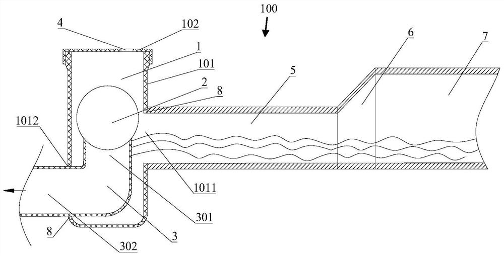
[0025] This embodiment provides an anti-blocking device 100 for an aeration pipe, such as figure 1 As shown in the figure, it includes a valve body 1, a liquid discharge pipe 3 and a float 2. The valve body 1 is used to communicate with the aeration pipe 7, one end of the liquid discharge pipe 3 is placed inside the valve body 1, and the other end of the liquid discharge pipe 3 extends Out of the valve body 1, the drain pipe 3 is connected to the inside and outside of the valve body 1. The drain pipe 3 is in sealing contact with the valve body 1. The floating ball 2 can close the upper end nozzle of the drain pipe 3, the valve body 1 is provided with a vent hole 4, and the height of the vent hole 4 is higher than the upper end nozzle of the liquid drain pipe 3. The float ball 2 and the upper end surface of the valve body 1 A certain distance is reserved to ensure that the float 2 can float normally. Among them, the valve body 1 and the aeration pipe 7 and the valve body 1 and...

Embodiment 2

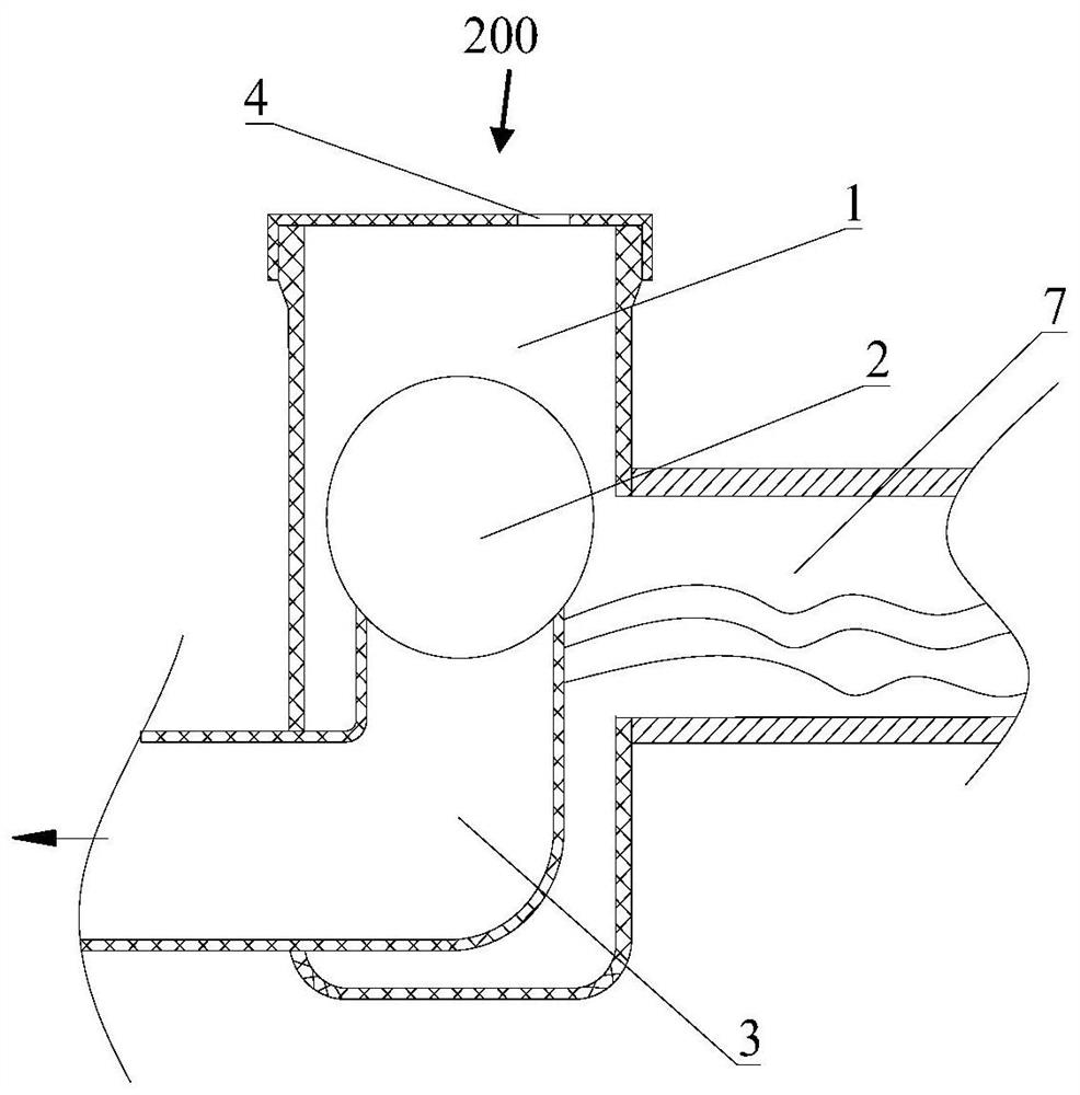
[0034] This embodiment provides an aeration device 200, such as figure 2 As shown, it includes the aeration pipe 7 and the aeration pipe anti-blocking device 100 in the first embodiment, and the valve body 1 communicates with the aeration pipe 7 . The aeration device 200 has a simple structure, is easy to apply, can automatically remove the leachate, avoids the phenomenon of insufficient supply caused by excessive leachate accumulated in the aeration pipe 7, improves the fermentation efficiency, and the leachate Discharge does not require manual participation, reducing the waste of manpower and energy.


PUM

PropertyMeasurementUnit
diameteraaaaaaaaaa

Abstract

The invention discloses an aeration pipe anti-blocking device, and relates to the compost aeration field, the aeration pipe anti-blocking device comprises a valve body, a liquid discharge pipe and a floating ball, the valve body is used for communicating with an aeration pipe, one end of the liquid discharge pipe is arranged in the valve body, the other end of the liquid discharge pipe extends out of the valve body, the liquid discharge pipe communicates with the inside and the outside of the valve body, and the liquid discharge pipe is in sealing contact with the valve body; the floating ball is arranged in the valve body and arranged at an upper end pipe opening of the liquid discharging pipe, the floating ball can seal the upper end pipe opening of the liquid discharging pipe, a vent hole is formed in the valve body, the height of the vent hole is larger than that of the upper end pipe opening of the liquid discharging pipe, and a distance is reserved between the floating ball and the upper end face of the valve body. The invention further discloses an aeration device comprising the anti-blocking device for the aeration pipe. The anti-blocking device for the aeration pipe and the aeration device provided by the invention are convenient to apply, can automatically discharge percolate, avoids blockage of the aeration pipe due to the fact that the percolate cannot be discharged in time, reduces the waste of manpower and energy, and improves the fermentation efficiency.

Description

technical field [0001] The invention relates to the technical field of compost aeration, in particular to an aeration pipe anti-blocking device and an aeration device. Background technique [0002] Aerobic composting technology, as the most fundamental, most economical and most effective method to deal with solid organic wastes, has gradually gained attention. The system usually uses the bottom aeration pipe for ventilation and oxygen supply, but there is often leachate in the aeration pipe, which causes the aeration holes to be blocked, and the oxygen supply is insufficient, which affects the fermentation effect. Usually the end of the aeration pipe is blocked with a pipe cap or valve. The blockage of the aeration pipe is not easy to detect in time, and it is necessary to manually open the end pipe cap or valve for ventilation and drainage, which wastes manpower and energy and affects the fermentation efficiency. SUMMARY OF THE INVENTION [0003] The purpose of the prese...

Claims


Application Information

Patent Timeline
Patent Type & Authority Applications(China)
IPC IPC(8): C05F17/979C05F17/986
CPCC05F17/979C05F17/986Y02W10/10
Inventor 马瑞强
Owner 中农创达(北京)环保科技有限公司
Why Eureka
Try Eureka