
Novel prefabricated steel reinforced concrete L-shaped composite shear wall structure

A combined shear wall and concrete technology, applied in building structures, walls, building components, etc., can solve the problems of complex connection nodes, lack of central tie knots, shear wall bulging, etc., and achieve simple connection nodes and central tension. The effect of binding material and preventing steel plate from bulging

Pending Publication Date: 2022-08-05
中建科技有限公司华东分公司
View PDF0 Cites 0 Cited by
  • Summary
  • Abstract
  • Description
  • Claims
  • Application Information

AI Technical Summary

Problems solved by technology

[0003] In order to solve the problems raised in the above-mentioned background technology, the object of the present invention is to provide a new type of prefabricated steel concrete L-shaped composite shear wall structure, which has the advantages of simple connection nodes, middle tie and material saving, and solves the problem of existing L-shaped steel structures. Composite shear wall joints are complicated, lack of central tie and waste materials. Steel plate shear walls on the market are generally composed of thinner steel plates. There is no standard connection method for wall-beam joints. Special treatment is required for wall-beam joints. The steel plate shear wall is generally long and lacks tie-tie measures in the middle, which may easily lead to buckling in the middle of the shear wall, while the web in the middle of the steel-steel beam shear wall only plays the role of tie-tie, which is a waste of materials

Method used


Image

  • Novel prefabricated steel reinforced concrete L-shaped composite shear wall structure
  • Novel prefabricated steel reinforced concrete L-shaped composite shear wall structure
  • Novel prefabricated steel reinforced concrete L-shaped composite shear wall structure

Examples


Embodiment Construction

[0025] The technical solutions in the embodiments of the present invention will be clearly and completely described below with reference to the accompanying drawings in the embodiments of the present invention. Obviously, the described embodiments are only a part of the embodiments of the present invention, rather than all the embodiments. Based on the embodiments of the present invention, all other embodiments obtained by those of ordinary skill in the art without creative efforts shall fall within the protection scope of the present invention.

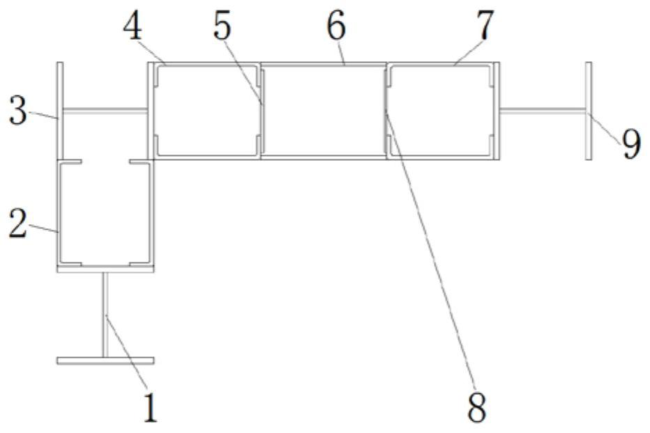
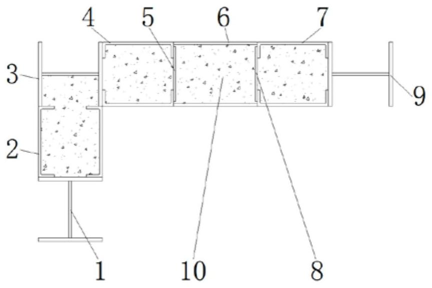
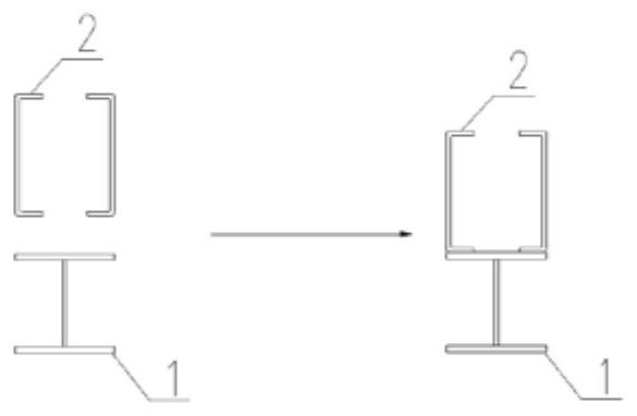
[0026] like Figure 1 to Figure 2 As shown in the figure, the novel prefabricated steel-concrete L-shaped composite shear wall structure provided by the present invention includes H-shaped steel 1, cold-formed channel steel 2, H-shaped steel 2 3, cold-formed channel steel 2 4, strip 5, steel plate 6. Cold-formed channel steel 3 7, strip 2 8, H-beam 3 9, concrete 10;

[0027] like Figure 3 to Figure 6 As shown, it is the concrete i...


PUM


Abstract

The invention discloses a novel prefabricated steel reinforced concrete L-shaped composite shear wall structure which comprises H-shaped steel I. The top of the H-shaped steel I is connected with cold-formed channel steel I in a welded mode, the top of the cold-formed channel steel I is connected with H-shaped steel II in a welded mode, and the right side of the H-shaped steel II is connected with cold-formed channel steel II in a welded mode. A first lacing bar is welded to the right side of the second cold-formed channel steel. By arranging the first H-shaped steel and the first cold-formed channel steel, the problems that an existing L-shaped steel combined shear wall is complex in connecting joint, lacks middle tie and wastes materials, steel plate shear walls in the market are generally composed of thin steel plates, no standard connecting method exists at the wall beam connecting position, the wall beam connecting position needs to be specially treated, and the construction cost is low are solved. The problems that a double-steel-plate shear wall is generally long, the middle of the double-steel-plate shear wall is short of tying measures, the middle of the shear wall is prone to bulging, a web in the middle of a steel pipe bundle shear wall only plays a tying role, and materials are wasted in use are solved.

Description

technical field [0001] The invention relates to the technical field of construction engineering, in particular to a novel prefabricated steel-concrete L-shaped composite shear wall structure. Background technique [0002] The L-shaped steel composite shear wall can be flexibly arranged in the structure according to the needs, avoiding convex beams and convex columns, and the steel structure part can be fully prefabricated in the factory, installed on site, multi-layer construction at the same time, free of formwork and support, and short construction period, especially suitable for In the high-rise residential system dominated by steel structures, L-shaped steel composite shear walls need to be used in the construction process. The existing L-shaped steel composite shear walls have complex connection nodes, lack of central knots and waste materials. The steel plate shear wall is generally composed of thinner steel plates. There is no standard connection method at the wall-be...

Claims


Application Information

Patent Timeline
Patent Type & Authority Applications(China)
IPC IPC(8): E04B2/60
CPCE04B2/60
Inventor 张孝栋明卿枢姜哲明李亮宫铭吴剑
Owner 中建科技有限公司华东分公司
Learn More