Wet-type spraying dust falling device for tunnel blasting

A dust-reducing device and wet-type technology, which is applied in spraying devices, safety devices, dust-proofing, etc., can solve problems such as unstable wind direction, failure to achieve dust removal effect, and low dust removal efficiency of fans.

Pending Publication Date: 2022-08-05
曾诚
View PDF0 Cites 0 Cited by
  • Summary
  • Abstract
  • Description
  • Claims
  • Application Information

AI Technical Summary

Problems solved by technology

[0004] In order to overcome the disadvantages of using a large fan to blow away the dust in the inner environment of the tunnel, the inner environment of the tunnel is relatively large, the dust removal efficiency of the fan alone is too low, and the wind direction is unstable, the dust cannot be blown away quickly, and the ideal dust removal effect cannot be achieved. The technical problem is: to provide a wet spray dust suppression device for tunnel blasting with good dust removal effect and flexible use

Method used


Image

  • Wet-type spraying dust falling device for tunnel blasting
  • Wet-type spraying dust falling device for tunnel blasting
  • Wet-type spraying dust falling device for tunnel blasting

Examples


Embodiment 1

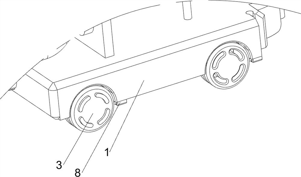
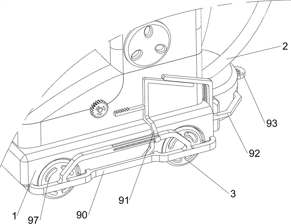
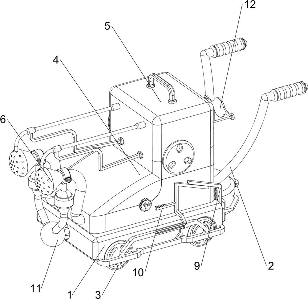
[0031] A wet spray dust suppression device for tunnel blasting, such as figure 1 , figure 2 , image 3 , Figure 5 , Image 6 and Figure 8 As shown, it includes a first support block 1, a first push rod 2, a transmission wheel 3, a water tank 4, a cover 5, a nozzle 6, a valve 7, a braking mechanism 9 and a rotating mechanism 11. The top right side of the first support block 1 is front and rear. The first push rod 2 is symmetrically arranged, and the front and rear sides of the first support block 1 are symmetrically provided with left and right rotations. There are four transmission wheels 3. The top of the first support block 1 is provided with a water tank 4, and the left side of the water tank 4 A spray head 6 is installed symmetrically on the side, front and rear, a cover 5 is slidably provided on the top of the water tank 4, a valve 7 is provided on the right side of the spray head 6, a braking mechanism 9 is arranged at the bottom of the first support block 1, and ...

Embodiment 2

[0038] On the basis of Example 1, as figure 1 , figure 2 , image 3 , Figure 4 , Figure 7 , Figure 9 and Figure 10 As shown, it also includes a mud scraping mechanism 8. The mud scraping mechanism 8 includes a limit block 80, a scraper 81 and a first return spring 82. The bottom of the first support block 1 is evenly provided with four limit blocks 80. The limit block 80 The scrapers 81 are slidably provided inside, and a first return spring 82 is connected between the scrapers 81 on the same side and the limit blocks 80 on the same side.

[0039] When people need to uniformly remove dust from the blasted tunnel interior environment, the drive wheel 3 will contact the ground inside the tunnel when it rotates, and the drive wheel 3 will be stained with a lot of soil. When the soil is in contact with the scraper 81, the scraper 81 will The soil will be scraped off, and the scraper 81 will always be in contact with the transmission wheel 3 under the action of the first...


PUM


Abstract

The invention relates to a dust falling device, in particular to a wet spraying dust falling device for tunnel blasting. The wet-type spraying dust falling device for tunnel blasting is good in dust removal effect and can be flexibly used. A wet-type spraying dust falling device for tunnel blasting comprises a first supporting block, a second supporting block, a first spraying device and a second spraying device, and four transmission wheels are symmetrically and rotationally arranged on the two sides in the first supporting block and used for enabling the device to move. People step on a pedal, a pressing rod moves downwards to drive an inclined rod to move leftwards, then a clamping rod moves leftwards to clamp a clamping block, the device stops moving and waits for a spray head to fully spray a key area, in this way, dust removal work can be conducted more flexibly, and the device does not need to be fixed manually.

Description

technical field [0001] The invention relates to a dust suppression device, in particular to a wet spraying dust suppression device for tunnel blasting. Background technique [0002] Tunnels are the key and key projects in the construction of highways and railways. With the development of railway construction and the advancement of science and technology, tunnel excavation methods have been developed rapidly. The next step is to disperse the dust. The general dispersing method is to use a large fan to blow the dust away. The internal environment of the tunnel is large, the dust removal efficiency of the fan alone is too low, and the wind direction is unstable, and the dust cannot be quickly blown away. Less than ideal dust removal effect. [0003] Therefore, it is necessary to design a wet spray dust suppression device for tunnel blasting with good dust removal effect and flexible use. SUMMARY OF THE INVENTION [0004] In order to overcome the disadvantages of using a lar...

Claims


Application Information

Patent Timeline
Patent Type & Authority Applications(China)
IPC IPC(8): E21F5/04B01D47/06B01D47/16B05B15/68B05B15/52B62B5/00
CPCE21F5/04B01D47/06B01D47/16B05B15/68B05B15/52B62B5/00Y02P70/10
Inventor 曾诚
Owner 曾诚
Why Eureka
Try Eureka