Eureka AIR delivers breakthrough ideas for toughest innovation challenges, trusted by R&D personnel around the world.

Boss and pit combined type blade air film cooling hole structure

A combined technology of air film cooling, applied in the direction of supporting elements of blades, climate sustainability, sustainable transportation, etc., can solve the problem of limited expansion of cooling air film, inability to effectively suppress the rise of cooling air flow, and inability to effectively control the mainstream and Cooling flow interaction and other issues to achieve the effect of increasing lateral coverage and suppressing lift

Pending Publication Date: 2022-08-05
SHENYANG AEROSPACE UNIVERSITY
View PDF0 Cites 0 Cited by
  • Summary
  • Abstract
  • Description
  • Claims
  • Application Information

AI Technical Summary

Problems solved by technology

However, these different cooling hole structures have a limited effect on the lateral (perpendicular to the flow direction) expansion of the cooling air film, and cannot effectively control the interaction between the main flow and the cooling flow, and cannot effectively suppress the lift of the cooling airflow.

Method used


Image

  • Boss and pit combined type blade air film cooling hole structure
  • Boss and pit combined type blade air film cooling hole structure
  • Boss and pit combined type blade air film cooling hole structure

Examples


Embodiment Construction

[0021] The present invention will be further described in detail below with reference to the accompanying drawings and specific embodiments.

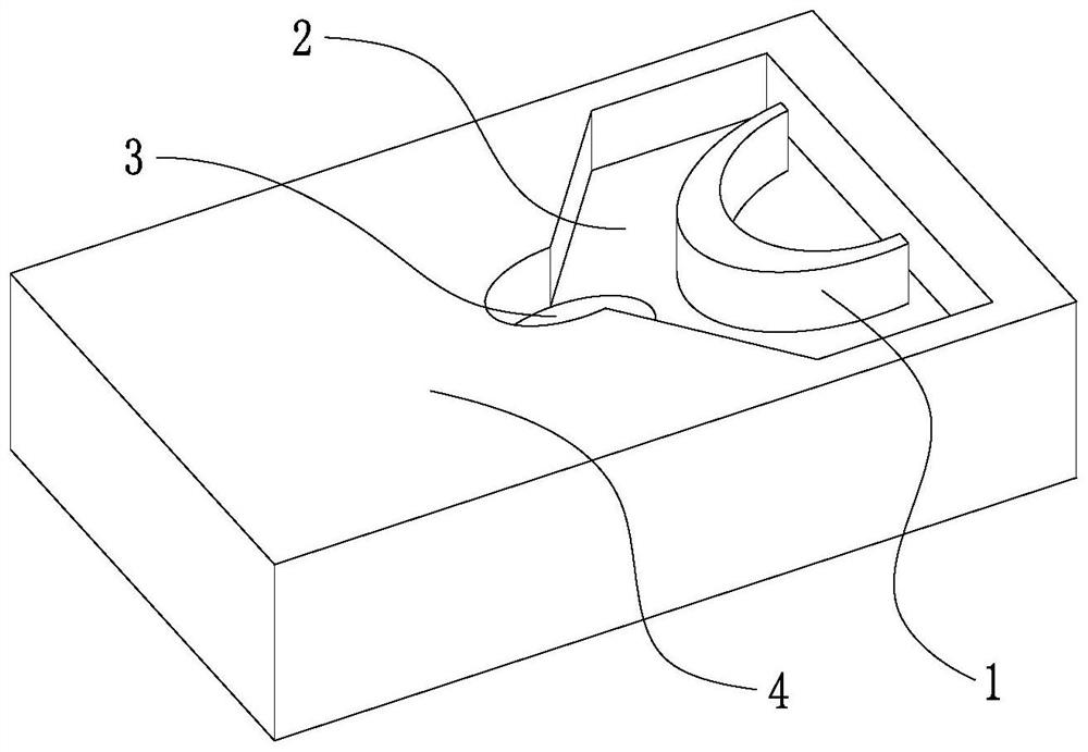
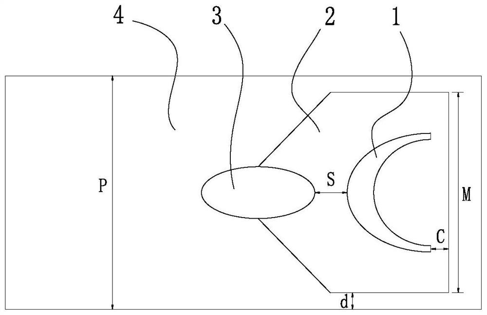
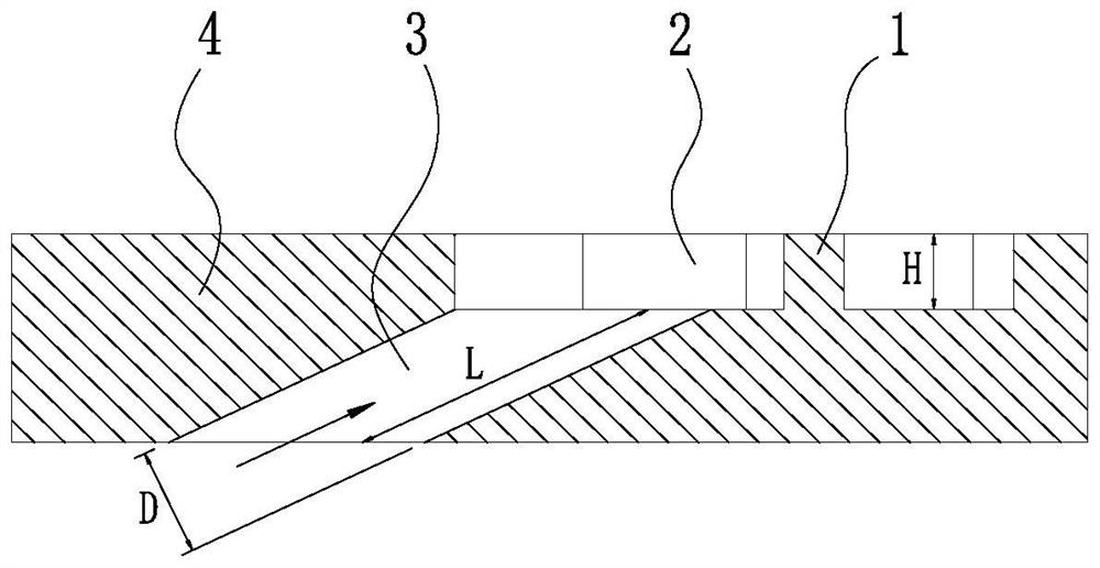
[0022] like Figures 1 to 3 As shown in the figure, a blade air film cooling hole structure combined with a boss and a pit includes a boss 1, a pit 2, a cylindrical hole 3 and a wall surface 4; the boss 1, the pit 2 and the cylindrical hole 3 are all provided with In the wall surface 4; the cylindrical hole 3 is communicated with the pit 2, and the outlet port of the cylindrical hole 3 is located on the bottom surface of the pit 2; the boss 1 is arranged in the pit 2, and the cylindrical hole The outlet port of 3 is directly opposite to the boss 1.

[0023] The centerlines of the boss 1 , the pit 2 and the cylindrical hole 3 are located in the same plane.

[0024] The height of the boss 1 is the same as the depth of the pit 2 .

[0025] The boss 1 is in the shape of a crescent as a whole, and the outlet port of the cylindrical hole 3...


PUM


Abstract

A boss and pit combined type blade air film cooling hole structure comprises a boss, a pit, a cylindrical hole and a wall face. The boss, the pit and the cylindrical hole are all arranged in the wall face, and the center lines of the boss, the pit and the cylindrical hole are located in the same plane. A hole opening in the air outlet end of the cylindrical hole is formed in the surface of the bottom of the pit; the boss is arranged in the concave pit, and the hole opening of the air outlet end of the cylindrical hole is right opposite to the boss. The boss is as high as the pit; the boss is integrally crescent-shaped, and the hole opening of the air outlet end of the cylindrical hole is opposite to the front edge surface of the boss; the cross section of the front edge surface of the boss is semi-elliptical, the cross section of the rear edge surface of the boss is semicircular, and the connection transition surface of the front edge surface and the rear edge surface of the boss is a plane; the section of the surface of the front section of the pit is semi-oval and is connected with an air outlet end orifice of the cylindrical hole, the section of the surface of the middle section of the pit is gradually expanded, and the section of the surface of the rear section of the pit is square. The transverse coverage range of the cooling air film can be increased, and the lifting of the cooling air flow is inhibited.

Description

technical field [0001] The invention belongs to the technical field of gas turbine and aero-engine blade cooling, in particular to a blade air film cooling hole structure combined with a boss and a pit. Background technique [0002] In order to further improve the output power and cycle efficiency of gas turbines and aero-engines, the usual practice is to continuously increase the turbine inlet temperature. However, the turbine inlet temperature of gas turbines and aero-engines is already much higher than the allowable temperature of high-temperature component materials. The operational safety and economy of the high-temperature components of aero-engines must be designed with efficient cooling technology. [0003] Existing cooling technologies mainly include divergent cooling, impingement cooling and film cooling. Among them, air film cooling is a cooling technology that uses a cooling air film to isolate the wall of the hot end part from the high temperature mainstream. T...

Claims


Application Information

Patent Timeline
IPC IPC(8): F01D5/18
CPCF01D5/186Y02T50/60
Inventor 贺业光张德恒杨天华李润东张涛
Owner SHENYANG AEROSPACE UNIVERSITY
Why Eureka
Eureka Blog
Learn More