Full-bore snap valve

A pull-off valve, full-bore technology, applied in the direction of lifting valves, valve devices, valve details, etc., can solve the problems of reducing the flow rate of loading and unloading, affecting work efficiency, obstructing media, etc., to facilitate installation and disassembly, and ensure work efficiency , Improve the effect of loading and unloading flow

Inactive Publication Date: 2022-08-05
连云港德安石化设备科技有限公司灌南分公司
View PDF0 Cites 0 Cited by
  • Summary
  • Abstract
  • Description
  • Claims
  • Application Information

AI Technical Summary

Problems solved by technology

When the flammable and explosive liquid is transported by a tank truck, it is necessary to connect the liquid from the storage tank storing the liquid to the interface of the tank truck through a pipeline, so that the liquid can enter the tank truck through the pipeline. The connection must be firm and tight, usually It is connected by flange bolts, which is safe but also has disadvantages. It takes a long time to connect and disassemble. Once an accident occurs, it is impossible to immediately stop the work of adding liquid to the tank car and make the tank car leave the site.
At present, other similar products adopt a valve form different from the present invention. There are parts that hinder the flow of the medium inside the pull-off valve, which increases the resistance of the flow, reduces the flow rate of loading and unloading, and reduces the work efficiency. Most users are not satisfied; When loading and unloading away from the pipeline, it seriously affects the work efficiency, especially when loading and unloading crude oil, asphalt and other poor fluidity media, the device has greater advantages. In addition, the existing product structure is complex and heavy, and it seriously breaks the principle of the pipeline when installed on the pipeline. Some balance increases the labor intensity of the staff

Method used


Image

  • Full-bore snap valve
  • Full-bore snap valve
  • Full-bore snap valve

Examples


Embodiment Construction

[0015] The specific technical solutions of the present invention are further described below, so that those skilled in the art can further understand the present invention, but do not limit the rights thereof.

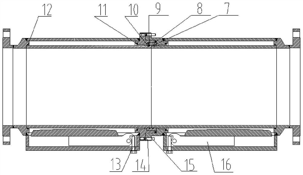
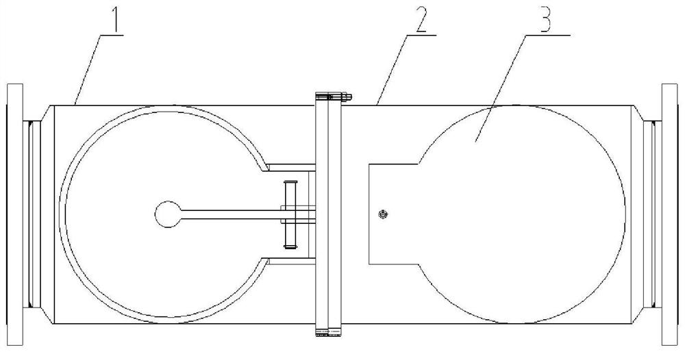
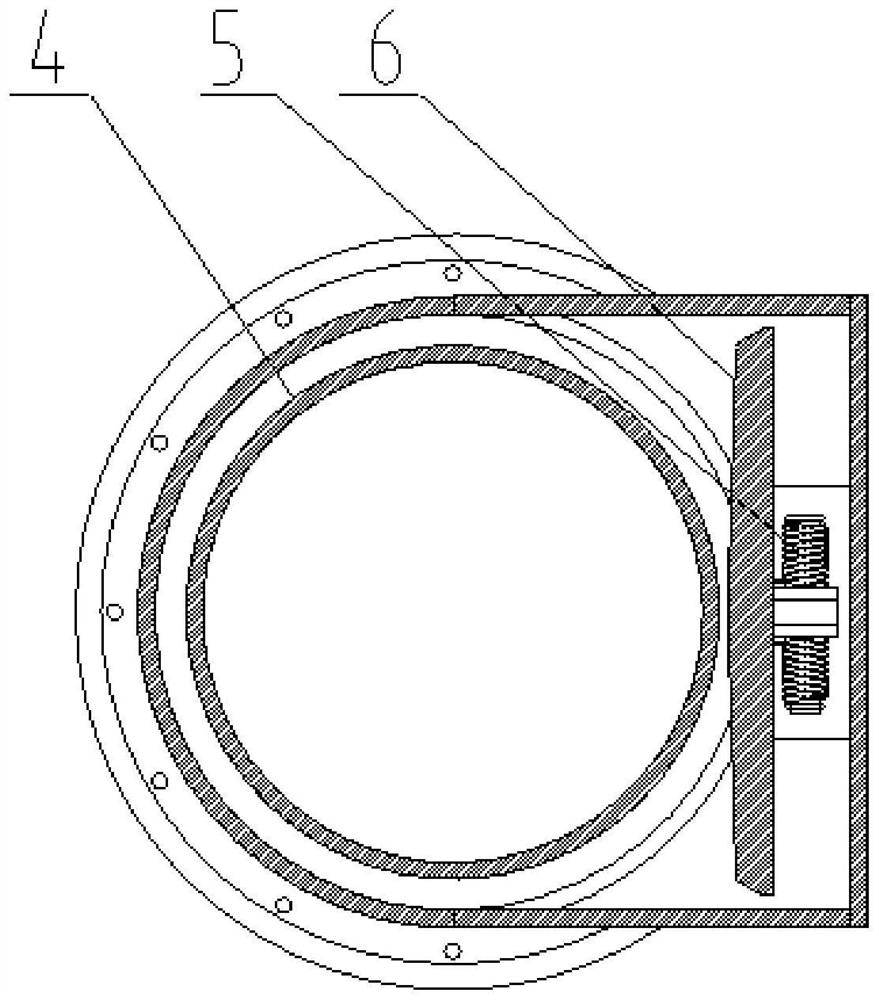
[0016] refer to Figure 1-Figure 3 , a full-bore pull-off valve, including two valve bodies installed in series on the pipeline, the connection of the valve bodies is provided with a butt flange 15, and the two valve bodies pass through a number of flanges installed along the circumferential direction. The two inner shells 4 are slidably installed inside the valve body to allow the medium to pass through unhindered, and a connecting sleeve 9 is installed at the connection between the two inner shells; Two rotary valve plate closing devices are arranged between the inner wall of the body and the outer wall of the inner casing for closing the pipe opening;

[0017] The rotary valve plate closing device includes a rotary valve plate 6 arranged in parallel with the direct...


PUM


Abstract

The invention discloses a full-bore break-away valve, and belongs to the field of flammable and explosive liquid conveying. Comprising two valve bodies installed on a pipeline in series, a butt joint flange is arranged at the joint of the valve bodies, the two valve bodies are connected through a plurality of snap bolts installed in the circumferential direction of the butt joint flange, two inner shells capable of allowing media to pass through without obstacles are installed in the valve bodies in a sliding mode, and a connecting sleeve is installed at the joint of the two inner shells; two rotary valve plate sealing devices used for sealing a pipeline opening are arranged between the inner wall of the valve body and the outer wall of the inner shell. The rotary valve plate sealing device comprises a rotary valve plate arranged in the central axis direction of the inner shell, a driving arm for driving the rotary valve plate to seal a pipeline port when the inner shell slides out of the valve body is installed between the rotary valve plate and the inner wall of the valve body, a fixing block is arranged on the valve body, one end of the driving arm is fixedly installed on the rotary valve plate, and the other end of the driving arm is hinged to the fixing block. And the driving arm drives the rotary valve plate to seal the pipeline port by taking the hinge point on the fixed block as a rotating shaft.

Description

technical field [0001] The invention relates to the field of inflammable and explosive liquid transportation, in particular to a full-bore pull-off valve. Background technique [0002] The pull-off valve is a safety protection device used in the process of loading and unloading flammable and explosive liquids. When flammable and explosive liquids are transported by tankers, it is necessary to connect the liquid from the storage tank for storing the liquid to the interface of the tanker through the pipeline, so that the liquid can enter the tanker through the pipeline. The connection must be firm and tight, usually It is connected with flange bolts, which is safe but also has the disadvantage that it takes a long time to connect and disassemble. Once an accident occurs, the work of adding liquid to the tanker cannot be stopped immediately and the tanker will leave the site. At present, other similar products use different valve forms than the present invention. There are par...

Claims


Application Information

Patent Timeline
Patent Type & Authority Applications(China)
IPC IPC(8): F16L29/00F16L23/036F16L23/02F16L23/18F16K1/20F16K1/32F16K27/02
CPCF16L29/00F16L23/036F16L23/02F16L23/18F16K1/2007F16K1/2042F16K1/32F16K27/0227
Inventor 金雷金建胜李小兰
Owner 连云港德安石化设备科技有限公司灌南分公司
Why Eureka
Try Eureka