Electric motor element and electric motor

A technology of motors and components, applied in the direction of magnetic circuit rotating parts, inorganic material magnetism, magnetic circuit shape/style/structure, etc., can solve problems such as poor molding processes, and achieve high output effects

Inactive Publication Date: 2017-03-22
PANASONIC INTELLECTUAL PROPERTY MANAGEMENT CO LTD
View PDF3 Cites 0 Cited by
  • Summary
  • Abstract
  • Description
  • Claims
  • Application Information

AI Technical Summary

Problems solved by technology

Therefore, there is a problem that, in the case of a molten body of a compound for bonded magnets with poor fluidity, problems may occur in the molding process.

Method used


Image

  • Electric motor element and electric motor
  • Electric motor element and electric motor
  • Electric motor element and electric motor

Examples


Embodiment 1

[0055] As the magnet powder constituting the bonded magnet, NdFeB-based magnet powder, SmFeN-based magnet powder, SmCo-based magnet powder, or the like can be used. One type of magnet powder may be used alone, or the above magnet powders may be used in combination. In order to be able to resist oxidation, it is better to use a coupling agent or a phosphoric acid coating to treat the surface of the magnet powder.

[0056] 96.5wt% of magnet powder, 3.0wt% of thermoplastic resin, and 0.5wt% of coupling agent were mixed, melted with a heating roll, kneaded and granulated to prepare magnet molding pellets. The roll temperature of the heating roll was set to 200°C.

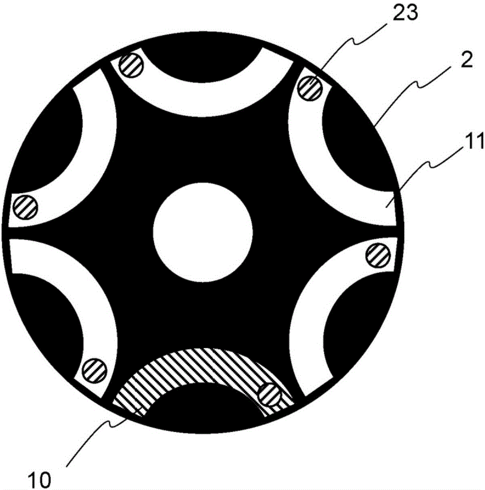
[0057] exist figure 2 Among them, the rotor 2 has a gate 23 near the outer peripheral portion of the end portion of the magnet arrangement hole 11 . Through the injection molding of the valve gate hot runner method, through the gate 23 to the figure 2 The magnet forming holes 11 provided inside the illustrated rot...

Embodiment 2

[0060] As the magnet powder constituting the bonded magnet, NdFeB-based magnet powder, SmFeN-based magnet powder, SmCo-based magnet powder, or the like can be used. One type of magnet powder may be used alone, or the above magnet powders may be used in combination. In order to be able to resist oxidation, it is better to use a coupling agent or a phosphoric acid coating to treat the surface of the magnet powder.

[0061] 96.5wt% of magnet powder, 3.0wt% of thermoplastic resin, and 0.5wt% of coupling agent were mixed, melted with a heating roll, kneaded and granulated to obtain pellets for magnet molding. The roll temperature of the heating roll was set to 200°C.

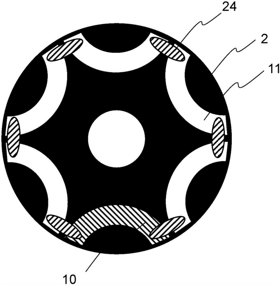
[0062] exist image 3 Among them, the rotor 2 has an elliptical gate 24 near the outer peripheral portion of the end portion of the magnet arrangement hole 11 . Through the injection molding of the valve gate hot runner method, through the gate 24 to the image 3 The magnet forming holes 11 provided inside the il...


PUM

PropertyMeasurementUnit
densityaaaaaaaaaa
densityaaaaaaaaaa

Abstract

The invention provides an electric motor element and an electric motor. The electric motor element comprises a rotor and a stator. A bonded magnet portion is a re-solidified body obtained by re-solidifying the molten material formed by melting a bonded magnet compound, and the bonded magnet portion has an outlet trace representing slag of outlet of a flow path at a position where the outlet of the flow path through which the melt is circulated is in contact with the bonded magnet portion. The outlet trace is located at the outer peripheral portion of the end face of the rotor (2) in the axial direction.

Description

technical field [0001] The present invention relates to a motor component and a motor on which a bonded magnet is mounted. Background technique [0002] Conventionally, when molding bonded magnets, injection molding has used a molding method that can handle flexible magnet shapes. However, with injection molding, when the resin is melted and filled into the mold, if the fluidity of the resin is not high, there is a problem that the mold cannot be filled sufficiently. Moreover, compared with compression molding, etc., injection Molding In order to improve the fluidity of pellets, it is necessary to increase the amount of resin. Therefore, the amount of magnet powder is relatively reduced, and thus, there is a problem that magnet properties are also lowered. [0003] In view of this problem, in order to improve the moldability, there is disclosed a polyamide resin composition for molding a magnetic material resin composite, which can improve fluidity during melting, dispersi...

Claims


Application Information

Patent Timeline
Patent Type & Authority Applications(China)
IPC IPC(8): H02K1/28H01F1/08
CPCH01F1/08H02K1/28
Inventor 堤慎一角治彦植田浩司浅井弘纪
Owner PANASONIC INTELLECTUAL PROPERTY MANAGEMENT CO LTD
Why Eureka
Try Eureka