Eye-protecting energy-saving lamp special for education

A technology for lamps and sliding rods, which is applied in the directions of energy-saving control technology, cleaning methods and appliances, cleaning methods using tools, etc., can solve the problems of reducing the electricity usage rate, failing to reduce the electricity usage rate, and cooling the lamps and lanterns by natural resources, etc. , to speed up the cooling rate and prevent the light from being too dark

Pending Publication Date: 2022-08-05
JIANGXI GUANGZHENG METAL EQUIP GRP CO LTD
View PDF7 Cites 0 Cited by
  • Summary
  • Abstract
  • Description
  • Claims
  • Application Information

AI Technical Summary

Problems solved by technology

[0005] In order to overcome the shortcomings of the above-mentioned patents that cannot use natural resources to cool down the lamps, and thus cannot reduce the utilization rate of electric energy, the technical problem to be solved is: provide a device that can use natural resources to cool down the lamps, thereby reducing electric energy. Utilization of eye-protecting energy-saving lamps for education

Method used


Image

  • Eye-protecting energy-saving lamp special for education
  • Eye-protecting energy-saving lamp special for education
  • Eye-protecting energy-saving lamp special for education

Examples


Embodiment 1

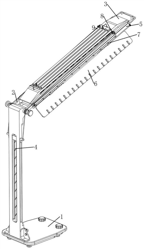
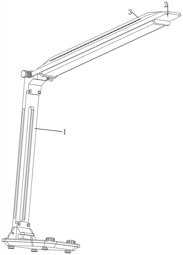
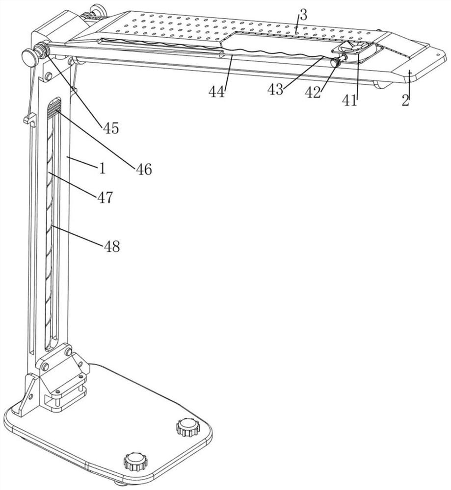
[0034] An eye protection energy-saving lamp specially used for education, such as Figure 1-7 As shown, it includes a base 1, a lamp 2, a heat dissipation plate 3, an energy-saving heat dissipation mechanism 4 and a water-cooled heat dissipation mechanism 5. A lamp 2 is rotatably connected to the upper side of the base 1, and the lamp 2 can illuminate the students. Heat dissipation plate 3, heat dissipation plate 3 can dissipate heat to lamp 2, heat dissipation plate 3 is provided with energy-saving heat dissipation mechanism 4, energy-saving heat dissipation mechanism 4 can perform energy-saving heat dissipation for lamp 2, lamp 2 is provided with water-cooled heat-dissipation mechanism 5, water-cooled heat-dissipation mechanism 5. The lamp 2 can be cooled down.

[0035] like figure 1 , image 3 and Figure 4 As shown, the energy-saving heat dissipation mechanism 4 includes a fan 41, a first sliding rod 42, a first spring 43, a pulling rope 44, a guide wheel 45, a movable ...

Embodiment 2

[0039] On the basis of Example 1, as figure 1 , Figure 8 and Figure 9 As shown, it also includes an adjustment mechanism 6 capable of concentrating the light source. The adjustment mechanism 6 includes a condensing plate 61, a rotating shaft 62, a first torsion spring 63, a clamping block 64, a fourth spring 65 and a second sliding rail 66, The front and rear sides of the lamp 2 are rotatably connected with a rotating shaft 62, and a condensing plate 61 is arranged on the rotating shaft 62, and the condensing plate 61 can condense the light source. The first torsion spring 63, the first torsion spring 63 can make the condensing plate 61 rotate and reset, the right side of the water tank 51 is provided with the second slide rail 66, the second slide rail 66 is slidably connected with the clamping block 64, the second slide The rail 66 can guide the clamping block 64, gears are provided on the right side of the rotating shaft 62, and the gears can facilitate the clamping blo...


PUM


Abstract

The invention relates to a lamp, in particular to an eye-protection energy-saving lamp special for education. The technical problem to be solved is to provide the special eye-protection energy-saving lamp for education, which can utilize natural resources to cool the lamp so as to reduce the utilization rate of electric energy. An eye-protection energy-saving lamp special for education comprises a base, a lamp body, a heat dissipation plate and the like, the lamp body is rotationally arranged on the upper side of the base, and the heat dissipation plate is arranged on the upper side of the lamp body. By turning on a lamp, illumination can be provided for people, by turning on a fan and then moving a movable plate downwards, the fan moves leftwards, the lamp can be fully cooled, then cold water is added into a water tank, and then people pull a stirring rod leftwards, so that the cold water in the water tank can be stirred; therefore, the cooling speed of the lamp can be increased.

Description

technical field [0001] The invention relates to a lamp, in particular to an eye protection energy-saving lamp specially used for education. Background technique [0002] In addition to the irregular reading distance, the reason for myopia is that when studying under the light, the light intensity is not enough and it is easy to cause myopia. [0003] The application publication number is CN209725939U, which discloses a special eye protection energy-saving lamp for education, which includes a top plate, a lampshade and a lamp body. The air duct, the two ends of the spiral air duct pass through the top plate and are respectively connected with the first exhaust fan and the second exhaust fan. When in use, the lamp body made of light-emitting diodes illuminates and generates heat at the same time. At the same time, the spiral air The first exhaust fan and the second exhaust fan at both ends of the pipe also start to work, forming a circulating air flow in the spiral air duct. ...

Claims


Application Information

Patent Timeline
IPC IPC(8): F21S6/00F21V14/00F21V29/56F21V29/67F21V33/00B08B1/00
CPCF21S6/002F21V29/67F21V29/56F21V14/00F21V33/00B08B1/00B08B1/12Y02B20/40
Inventor 杨金光方强
Owner JIANGXI GUANGZHENG METAL EQUIP GRP CO LTD
Why Eureka
Try Eureka