
High-power bandwidth filter

A filter, high-power technology, applied in the direction of instruments, optical waveguide coupling, optical guides, etc., can solve the problems of low withstand power, poor dispersion effect, etc., to improve withstand power, reduce temperature rise, and good heat dissipation effect. Effect

Pending Publication Date: 2022-08-05
珠海光焱科技有限公司
View PDF7 Cites 0 Cited by
  • Summary
  • Abstract
  • Description
  • Claims
  • Application Information

AI Technical Summary

Problems solved by technology

However, the power of the filters currently on the market is low, and the dissipation effect is poor; it is difficult to find a high-power filter that meets the needs of users in the existing optical filter market

Method used


Image

  • High-power bandwidth filter
  • High-power bandwidth filter
  • High-power bandwidth filter

Examples


Embodiment Construction

[0017] The present invention will be further described in detail below with reference to the accompanying drawings and specific embodiments. The numbers of the steps in the following embodiments are only set for the convenience of description, and the sequence between the steps is not limited in any way, and the execution sequence of each step in the embodiments can be adapted according to the understanding of those skilled in the art Sexual adjustment.

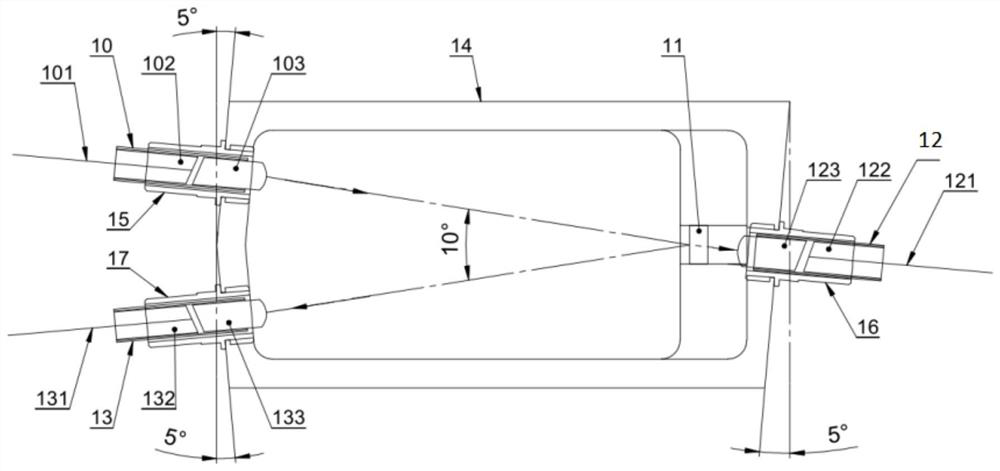
[0018] like figure 1 As shown, an embodiment of the present invention provides a high-power bandwidth filter, comprising a box body, an optical input module, a first optical output module and a second optical output module arranged on the box body, and an optical input module arranged inside the box body. Band-pass filter; wherein, the first side of the band-pass filter is coated with a band-pass film and the second side is coated with an anti-reflection film, the light input module and the second light output module and the...


PUM


Abstract

The invention discloses a high-power bandwidth filter which comprises a box body, an optical input module, a first optical output module and a second optical output module which are arranged on the box body, and a band-pass optical filter arranged in the box body, wherein the first side face of the band-pass optical filter is plated with a band-pass film, the second side face of the band-pass optical filter is plated with an antireflection film, the included angle between the optical input module and the band-pass optical filter is equal to the included angle between the second optical output module and the band-pass optical filter, and the first optical output module is located on the extension line of the optical input module. The band-pass optical filter is arranged on a connecting line between the optical input module and the first optical output module, and a band-pass film of the band-pass optical filter faces the optical input module. The embodiment of the invention can improve the bearing power of the bandwidth filter, is good in heat dissipation effect, and can be widely applied to the technical field of optical devices.

Description

technical field [0001] The present invention relates to the technical field of optical devices, in particular to a high-power bandwidth filter. Background technique [0002] The fiber filter designed according to the principle of optical interference is mainly used to filter out the useless frequency (wavelength) components in the signal. For example: a narrow-band signal with a center wavelength of 1064 nm, which contains a larger range of other wavelengths of interference signals. With the demand for wavelength selection in the fields of optical fiber communication, optical fiber sensing, optical information processing, and fiber lasers, higher requirements are placed on the withstand power of the filter. However, the withstand power of filters in the current market is relatively low, and the dispersion effect is poor; it is difficult to find high-power filters that meet the needs of users in the existing optical filter market. SUMMARY OF THE INVENTION [0003] In view...

Claims


Application Information

Patent Timeline
IPC IPC(8): G02B6/293G02B6/42
CPCG02B6/29368G02B6/4215G02B6/4268
Inventor 陆继乐蔡宣盘赵德平段誉曹丁象徐迎彬谢昌斌王碧明雷芬芬刘文东卢子荣于浩然
Owner 珠海光焱科技有限公司
Learn More