Broadband low-loss directional coupler and frequency modulation transmitter system
A directional coupler, low-loss technology, applied in the transmission system, reducing energy consumption, waveguide devices, etc., can solve the problem of not being able to take into account small size and broadband at the same time, achieve low insertion loss, realize transmission and coupling, easy integrated effect
- Summary
- Abstract
- Description
- Claims
- Application Information
AI Technical Summary
Problems solved by technology
Method used
Image

Examples
Embodiment 1
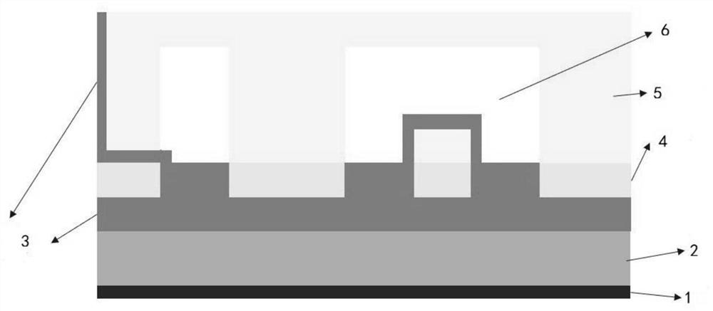
[0051] When designing a broadband low-loss directional coupler based on IPD, ADS software is used on the computer to design and simulate a small-sized directional coupler based on the IPD process and composed of LC cell topology results; its substrate structure is as follows figure 1 As shown, it includes a metal ground 1, a GaAs substrate 2 as a load-carrying body, a SiNx dielectric layer 3, a first metal layer 4, a second metal layer 5 and an air bridge structure 6 stacked on the GaAs substrate 2 in sequence; The first metal layer 4 (20nmTi / 80nm Au) grown by radiation; the lower metal layer (4.5μm Cu / 0.5μm Au) generated by the electroplating process; the SiNx dielectric layer 3 serving as the dielectric between the upper and lower plates of the capacitor, in which part of the SiNx passes through After dry etching, through holes required in the design structure are formed; electroplating metal is used to form the "bridge pier" structure in the air bridge structure 6; the secon...
Embodiment 2
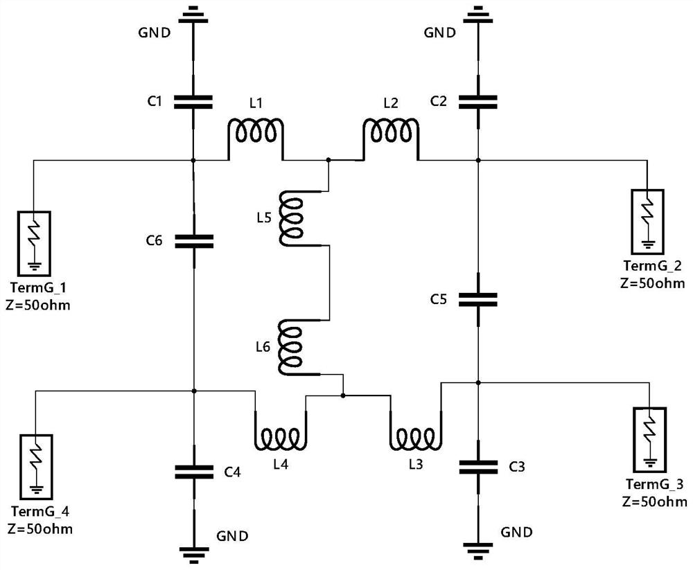
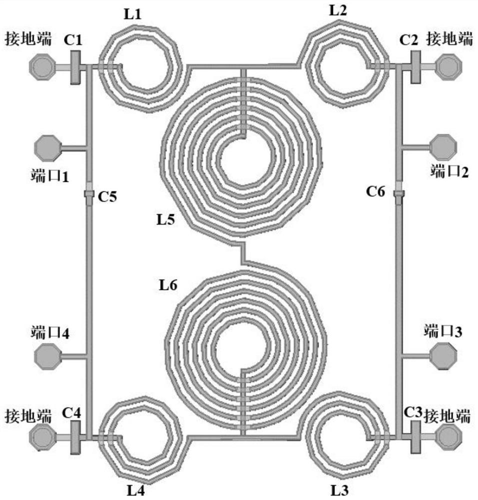
[0054] The first-order circuit topology of the broadband low-loss directional coupler proposed by the present invention is composed of two main circuits, three branches interconnected by the main circuits, and four ground bypasses, such as figure 2 The circuit topology diagram of , the circuit structure is center-symmetric about the center point of the inductive branch interconnected by the main circuit. In the circuit topology diagram of the directional coupler (1st order), it includes four inductors L (L1, L2, L3, L4) on the two main circuits, and four capacitors C (C1, C2, C3, C4), L (L5, L6) on the inductive branch formed by the interconnection of the two main circuits, and C (C5, C6) on the two capacitive branches formed by the interconnection of the two main circuits. The first-order directional coupler circuit topology diagram is connected to each part of the components in the circuit result, and then the components of the layout are used to replace each part L and C a...
Embodiment 3
[0057] A transmitter is a device that can transmit a signal at a certain frequency. It is widely used in various civil and military equipment such as television, radio, communication, alarm, radar, remote control, telemetry, and electronic countermeasures. The directional coupler is an important part of the FM transmitter system, which is directly related to the broadcast quality of the broadcast signal and the operation safety of the broadcast transmitter equipment. Therefore, a directional coupler with small size and excellent performance is very necessary for the realization of some circuits that realize specific functions and to improve the performance in FM transmitters. The novel microwave broadband low-loss directional coupler proposed in the present invention is a weakly coupled directional coupler (coupling degree <-20dB), which is often set at the input and output terminals of the FM transmitter at all levels. In the coaxial line, it is used to provide signals for me...
PUM
 Abstract
Description
Claims
Application Information
 - R&D Engineer
- R&D Manager
- IP Professional
- Industry Leading Data Capabilities
- Powerful AI technology
- Patent DNA Extraction
Browse by: Latest US Patents, China's latest patents, Technical Efficacy Thesaurus, Application Domain, Technology Topic.
© 2024 PatSnap. All rights reserved.Legal|Privacy policy|Modern Slavery Act Transparency Statement|Sitemap