
Plate type wire clamping device

A clamping and plate-type technology, applied in the direction of clamping/spring connection, connecting contact materials, electrical components, etc., can solve problems such as poor contact, stress relaxation, and uncompressed wires, and achieve low production costs and reduce contact The effect of resistance, clamping and fastening is firm

Pending Publication Date: 2022-08-05
STATE GRID CHONGQING ELECTRIC POWER +1
View PDF0 Cites 0 Cited by
  • Summary
  • Abstract
  • Description
  • Claims
  • Application Information

AI Technical Summary

Problems solved by technology

[0004] The purpose of the present invention is to provide a plate-type wire clamping device to solve the problems of stress relaxation and poor contact caused by unpressed wires

Method used


Image

  • Plate type wire clamping device
  • Plate type wire clamping device
  • Plate type wire clamping device

Examples


Embodiment Construction

[0025] The principles and features of the present invention will be described below with reference to the accompanying drawings. The examples are only used to explain the present invention, but not to limit the scope of the present invention.

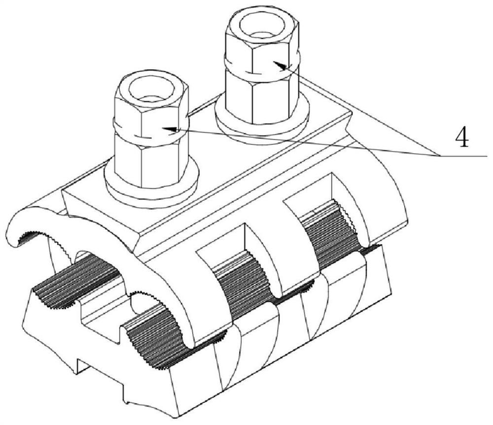
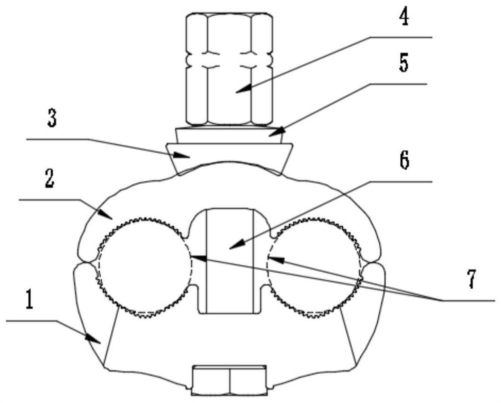
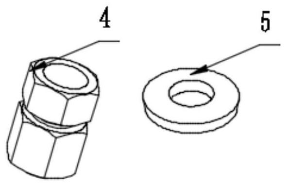
[0026] like figure 1 and 2 As shown, a plate-type wire clamping device includes an upper clamping plate 2 and a lower clamping plate 1, and two corresponding arc-shaped grooves 11 are arranged on the side where the upper clamping plate 2 and the lower clamping plate 1 are attached to each other, and the upper clamping plate 2 and the lower clamping plate 1. Clamp and fix the side of the upper splint 2 and the lower splint 1 of the fixed wire 7 through the set arc-shaped grooves, and set a lengthwise weight-reducing groove between the two arc-shaped grooves 11 . The upper splint 2 and the lower splint 1 are correspondingly provided with at least one bolt through hole 14 between the two arc-shaped grooves 11, and the upper splint 2 and t...


PUM


Abstract

The invention relates to the field of power systems, in particular to a plate type wire clamping device which comprises an upper clamping plate and a lower clamping plate, two corresponding arc-shaped grooves are formed in the sides, attached to each other, of the upper clamping plate and the lower clamping plate, and the upper clamping plate and the lower clamping plate clamp and fix a wire through the formed arc-shaped grooves; the upper clamping plate and the lower clamping plate are correspondingly provided with at least one bolt between the two arc-shaped grooves; the arc-shaped groove is also provided with a clamping part which is used for clamping and fastening a wire. The side, attached to the fastening bolt, of the lower clamping plate is further provided with a clamping groove, the groove edge of the clamping groove is used for clamping at least one set of opposite edges of the bolt head of the fastening bolt, and the fastening bolt is prevented from rotating in the clamping groove. A surface oxide layer of the wire can be conveniently pierced, the contact performance between the upper clamping plate and the wire and between the lower clamping plate and the wire is improved, and the contact resistance is effectively reduced; and meanwhile, the upper clamping plate, the lower clamping plate and the wire are clamped and fastened more firmly. The clamping groove is formed in the lower clamping plate, and high-altitude installation operation can be greatly facilitated.

Description

technical field [0001] The invention relates to the field of electric power systems, in particular to a plate-type wire clamping device. Background technique [0002] The new type of fastening device is a non-load-bearing connection device, which is mainly used in transmission lines, substation lines and distribution line systems, and plays the role of wire jumper conversion connection. [0003] Traditional non-load-bearing connections mostly use JBLY reducing fasteners, C-type fasteners, J-type fasteners or JXL Amp fasteners. Such devices have many shortcomings: 1. Such devices generally have low material strength and large metal creep. 2. At present, the conventional nut is used for locking, which is easily affected by human factors during installation, resulting in a small tightening torque, which leads to the uncompressed wire caused by improper installation, which seriously affects the safe operation of the power grid. 3. The device adopts conventional standard spring...

Claims


Application Information

Patent Timeline
Patent Type & Authority Applications(China)
IPC IPC(8): H01R4/44H01R4/62H01R4/2407H01R4/2408H01R4/30
CPCH01R4/44H01R4/62H01R4/301H01R4/2407H01R4/2408
Inventor 冯德伦邓小勇苑吉河唐击张曦张毅熊杰康昊天王梅黄文谦
Owner STATE GRID CHONGQING ELECTRIC POWER
Learn More