Press fitting device for micro fan impeller

A press-fitting device and micro-fan technology, which is applied in wind power generation, metal processing equipment, metal processing, etc., can solve the problems affecting the dynamic balance and noise of the fan, the deviation of the rotor shaft and the impeller hole, and the large runout of the impeller and the shaft. , to achieve the effect of high press-fitting safety, elimination of dynamic balance and noise, and high press-fitting accuracy

Pending Publication Date: 2022-08-09
南京锚点流体科技有限公司
View PDF0 Cites 0 Cited by
  • Summary
  • Abstract
  • Description
  • Claims
  • Application Information

AI Technical Summary

Problems solved by technology

[0002] The impeller and rotor shaft of the existing press-fitting mechanism are press-fitted using the outer circle of the impeller for positioning and pressing. The rotor shaft and the impeller hole are offset, the guide is not good, and the rotor shaft is bent due to excessive force, resulting in product scrapping, or the impeller and shaft The jump is large, which affects the dynamic balance and noise of the fan

Method used


Image

  • Press fitting device for micro fan impeller
  • Press fitting device for micro fan impeller
  • Press fitting device for micro fan impeller

Examples


Embodiment Construction

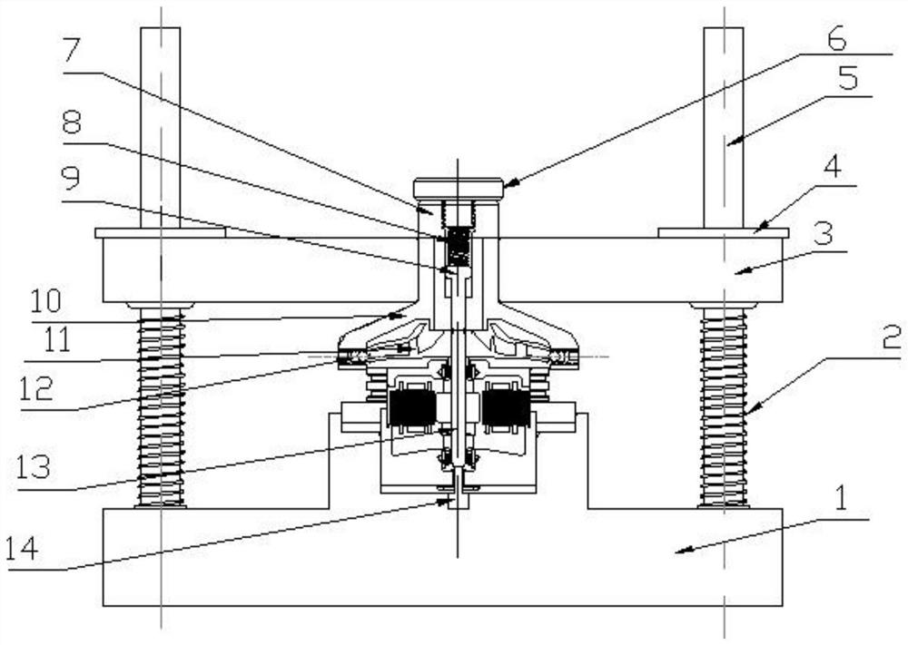
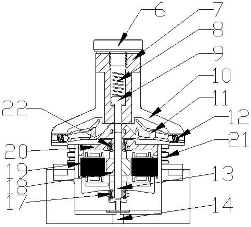
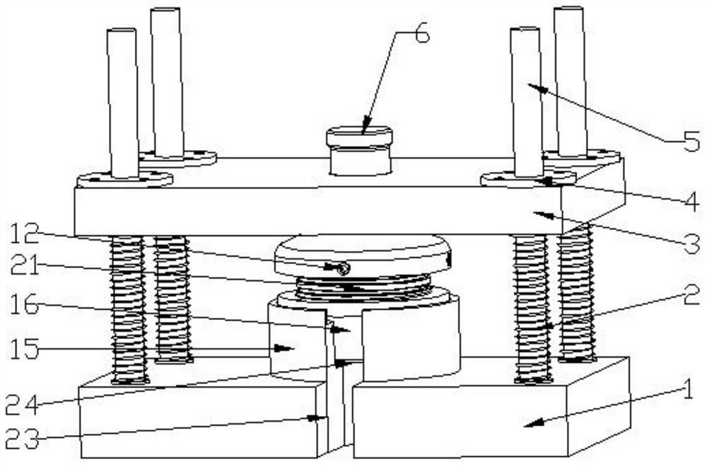
[0019] like Figure 1-4 As shown, a micro-fan impeller press-fitting device includes a positioning base plate 1, a plurality of guide rails 5 are symmetrically installed on the upper end of the positioning base plate 1, and an upper movable positioning plate 3 is slidably connected between the left and right guide rails 5. The positioning plate 3 moves up and down under the limiting action of the guide rail 5. The guide rail 5 between the upper movable positioning plate 3 and the positioning bottom plate 1 is sleeved with a spring 2, and the spring 2 can release the upper movable positioning plate 3 from being pressed. state, make it return to its original position, and prepare for the next press-fitting. An impeller fixing plate 10 is installed in the center of the movable positioning plate 3. The impeller fixing plate 10 elastically fixes the impeller 11 through a plurality of spring plungers 12. A movable guide pin sleeve 7 is installed in the shaft hole of the impeller 11,...


PUM


Abstract

The miniature fan impeller press-fitting device comprises a positioning bottom plate, a plurality of guide rails are arranged at the upper end of the positioning bottom plate in a bilateral symmetry mode, an upper movable positioning plate is slidably connected between the left guide rail and the right guide rail, and springs are arranged on the guide rails between the upper movable positioning plate and the positioning bottom plate in a sleeving mode; an impeller fixing disc is arranged in the center of the movable positioning plate and elastically fixes an impeller through a plurality of spring plungers, a movable guide pin sleeve is arranged in a shaft hole of the impeller, and a movable guide pin is arranged in the movable guide pin sleeve; a bolt cover is arranged at the upper end of the movable guide pin sleeve; a small spring is arranged between the movable guide pin and the bolt cover; a fan shell positioning cavity is formed in the center of the positioning bottom plate, a fan shell is arranged in the fan shell positioning cavity, a lifting pin is arranged at the bottom of the fan shell, and the upper end face of the lifting pin makes contact with a rotor shaft. In conclusion, the press-fitting device is easy to assemble and disassemble, high in press-fitting precision, good in quality and high in press-fitting safety.

Description

technical field [0001] The invention relates to the technical field of fan press-fitting, in particular to a micro-fan impeller press-fitting device. Background technique [0002] In the existing press-fitting mechanism, the impeller and the rotor shaft are press-fitted by the outer circle of the impeller, and the rotor shaft and the impeller hole are misaligned, and the guidance is not good. The beating is large, which affects the dynamic balance and noise of the fan. Based on this, the present invention proposes a press-fitting device for the impeller of a micro-fan. SUMMARY OF THE INVENTION [0003] The purpose of the present invention is to provide a micro-fan impeller press-fitting device to solve the above-mentioned problems. [0004] In order to solve the above-mentioned technical problems, the present invention adopts the following technical solutions: [0005] The present invention is a micro-fan impeller press-fitting device, comprising a positioning bottom pl...

Claims


Application Information

Patent Timeline
Patent Type & Authority Applications(China)
IPC IPC(8): B23P19/02
CPCB23P19/02Y02E10/72
Inventor 周培良陈宇豪汪平魏毅波
Owner 南京锚点流体科技有限公司
Why Eureka
Try Eureka