Mechanical planarization apparatus

A mechanical flattening and equipment technology, applied in metal processing equipment, grinding/polishing equipment, grinding machine parts, etc., can solve the problem that the jaws cannot clamp wafers with trimmed edges, etc. Improve the quality of processing, reduce the contact area, and reduce the effect of residue

Active Publication Date: 2022-08-09
BEIJING SEMICORE PRECISION MICROELECTRONICS EQUIP CO LTD
View PDF4 Cites 2 Cited by
  • Summary
  • Abstract
  • Description
  • Claims
  • Application Information

AI Technical Summary

Problems solved by technology

[0003] Therefore, in order to solve the defect that the existing jaws cannot clamp the wafer with trimming, a kind of mechanical planarization equipment is provided, which includes:

Method used


Image

  • Mechanical planarization apparatus
  • Mechanical planarization apparatus
  • Mechanical planarization apparatus

Examples


Embodiment Construction

[0049] The technical solutions of the present invention will be clearly and completely described below with reference to the accompanying drawings. Obviously, the described embodiments are part of the embodiments of the present invention, but not all of the embodiments. Based on the embodiments of the present invention, all other embodiments obtained by those of ordinary skill in the art without making creative efforts shall fall within the protection scope of the present invention.

[0050] In the description of the present invention, it should be noted that the terms "center", "upper", "lower", "left", "right", "vertical", "horizontal", "inner", "outer", etc. The indicated orientation or positional relationship is based on the orientation or positional relationship shown in the accompanying drawings, which is only for the convenience of describing the present invention and simplifying the description, rather than indicating or implying that the indicated device or element mus...


PUM


Abstract

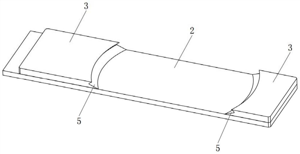
The invention provides a clamping jaw and mechanical planarization equipment, and belongs to the technical field of wafer mechanical planarization, the clamping jaw comprises a polishing unit, a scrubbing unit, a drying unit and a manipulator, the manipulator comprises a mechanical arm and a clamping jaw connected to the mechanical arm; the clamping jaw comprises a mounting plate, two clamping pieces and a driving piece, the two clamping pieces are both connected to the mounting plate, and the driving piece is connected with at least one clamping piece and used for driving the two clamping pieces to move close to or away from each other. Clamping faces are symmetrically arranged on the side portions, close to each other, of the two clamping pieces, the clamping faces are arc faces with the radius consistent with the radius of the wafer, and the chord length corresponding to the arcs of the clamping faces is larger than the trimming length of the wafer. Through the arrangement of the clamping faces, the clamping jaw can clamp and position a standard circular wafer and a wafer with a cut edge, the structure is simple and reliable, and the positioning precision in the wafer carrying process is improved.

Description

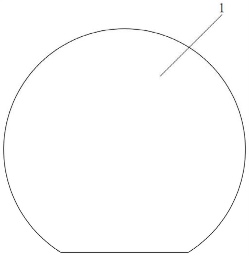
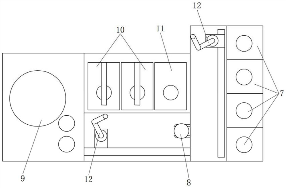
technical field [0001] The present invention relates to the technical field of wafer mechanical planarization, in particular to a mechanical planarization device. Background technique [0002] refer to figure 1 , Wafers made of third-generation semiconductor materials will have a trimmed edge. At present, common mechanical planarization equipment is mainly for polishing wafers with a standard circular shape, and polishing wafers with trimmed edges. When it is used, there will be problems of inaccurate positioning and deviation of the center of the circle due to the existence of trimming, which will seriously affect the processing quality of the wafer. question. SUMMARY OF THE INVENTION [0003] Therefore, in order to solve the defect that the existing clamping jaws cannot clamp wafers with trimmed edges, a mechanical planarization device is provided, which includes: [0004] storage boxes for storing wafers; [0005] a polishing unit, arranged on one side of the storag...

Claims


Application Information

Patent Timeline
Patent Type & Authority Applications(China)
IPC IPC(8): B24B29/02B24B41/06B24B41/00
CPCB24B29/02B24B41/06B24B41/00Y02P70/50
Inventor 史霄尹影费玖海舒福璋吴尚东
Owner BEIJING SEMICORE PRECISION MICROELECTRONICS EQUIP CO LTD
Why Eureka
Try Eureka