Vibration-damper for steel sheet

A vibration damping device and steel plate technology, which is applied in the field of steel plate vibration damping devices, can solve the problems of electromagnet and steel plate contact, vibration increase, etc.

Inactive Publication Date: 2004-10-13
SHINKO ELECTRIC CO LTD
View PDF0 Cites 2 Cited by
  • Summary
  • Abstract
  • Description
  • Claims
  • Application Information

AI Technical Summary

Problems solved by technology

Therefore, the vibration increases, especially in the initial stage of the electromagnet avoidance action, that is, the stage when the dis

Method used


Image

  • Vibration-damper for steel sheet
  • Vibration-damper for steel sheet
  • Vibration-damper for steel sheet

Examples


Embodiment Construction

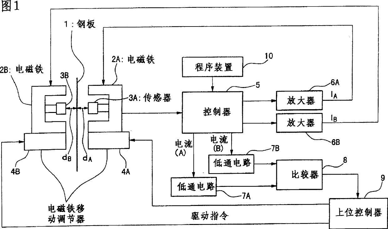
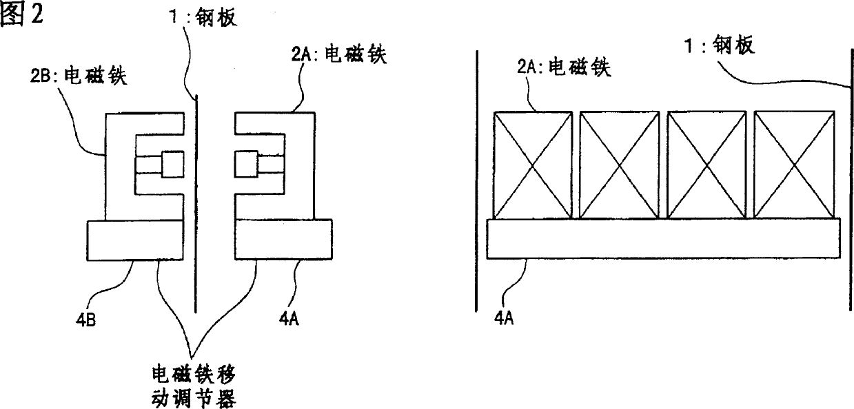
[0050]The configuration of Embodiment 1 of the present invention is shown in FIG. 1 . The steel plate 1 moves from the bottom to the top in the figure. In this figure, a picture of the steel plate 1 viewed from the side is shown. An electromagnet 2A is provided on the front side of the moving steel plate 1, and an electromagnet 2B is provided on the back side. The electromagnets 2A and 2B are installed at positions opposing to each other across the steel plate 1 . In the electromagnet 2A, a sensor 3A for detecting the distance from the electromagnet to the steel plate 1 is provided, and in the electromagnet 2B, a sensor 3B for detecting the distance is also provided. The detection surface of the sensor 3A is on the same surface as the magnetic pole surface of the electromagnet 2A, and the detection surface of the sensor 3B is on the same surface as the magnetic pole surface of the electromagnet 2B. Both the sensors 3A and 3B are installed at positions facing each other acro...


PUM


Abstract

To provide a damping device with which stable damping is enabled without loss of damping effect. The damping device for steel sheets is provided with electromagnets 2A, 2B for applying magnetic force in a direction crossed with the steel sheet to executing damping of the traveling steel sheet, sensors 3A, 3B for detecting the distances between these electromagnets and the steel sheet, controller 5 for controlling the exciting current which is flown to the electromagnets based on the distances detected with these sensors and actuators 4A, 4B for adjusting the distances between the electromagnets and the steel sheet. Subjecting to that the electromagnets and steel sheet becomes a specific positional relation, and the distances between the electromagnets and the steel sheet are adjusted with the actuators.

Description

technical field [0001] The present invention relates to a steel plate vibration damping device, which suppresses the vibration of a strip-shaped steel plate moving on its flowing working surface in a rolling production line, a surface treatment production line, etc. of steelmaking equipment. Background technique [0002] As shown in FIG. 14 , a conventional damping device uses electromagnets 2A and 2B disposed opposite to each other on the front side and back side of the steel plate 1 to sandwich the moving steel plate 1 to suppress the vibration of the moving steel plate 1 . [0003] In such a vibration damping device, for example, sensors 3A and 3B for detecting the distance from the magnetic pole surfaces of the electromagnets 2A and 2B to the steel plate 1 are provided in the electromagnets 2A and 2B, and these sensors 3A and 3B detect The distance between them controls the excitation current flowing in the electromagnets 2A and 2B. As a result, the vibration of the movi...

Claims


Application Information

Patent Timeline
IPC IPC(8): B21B37/00B21B39/14B21C47/34B65H23/10B65H77/00C21D9/56
CPCC21D9/562B65H2511/22B21C47/34B65H23/10B21B39/14B65H2511/51B21B37/007B65H2515/50B65H2220/01B65H2220/02B21B37/46B21B38/00B21B2203/44
Inventor 木村哲行村岸恭次加藤一路
Owner SHINKO ELECTRIC CO LTD
Why Eureka
Try Eureka