Objective lens driving device

A technology of driving device and objective lens, applied in beam guiding device, configuration/installation of head, instrument, etc., can solve the problems of difficult magnetic circuit and increased number of parts, etc.

Inactive Publication Date: 2004-11-03
HITACHI LTD +1
View PDF0 Cites 0 Cited by
  • Summary
  • Abstract
  • Description
  • Claims
  • Application Information

AI Technical Summary

Problems solved by technology

Also, it is difficult to use a general-purpose magnetic circuit, because each part needs to be used separately, so the number of parts is expected to increase

Method used


Image

  • Objective lens driving device
  • Objective lens driving device
  • Objective lens driving device

Examples


Embodiment Construction

[0051] The preferred embodiments of the present invention will be described below in conjunction with the drawings.

[0052] First, the first embodiment of the objective lens driving device of the present invention will be explained.

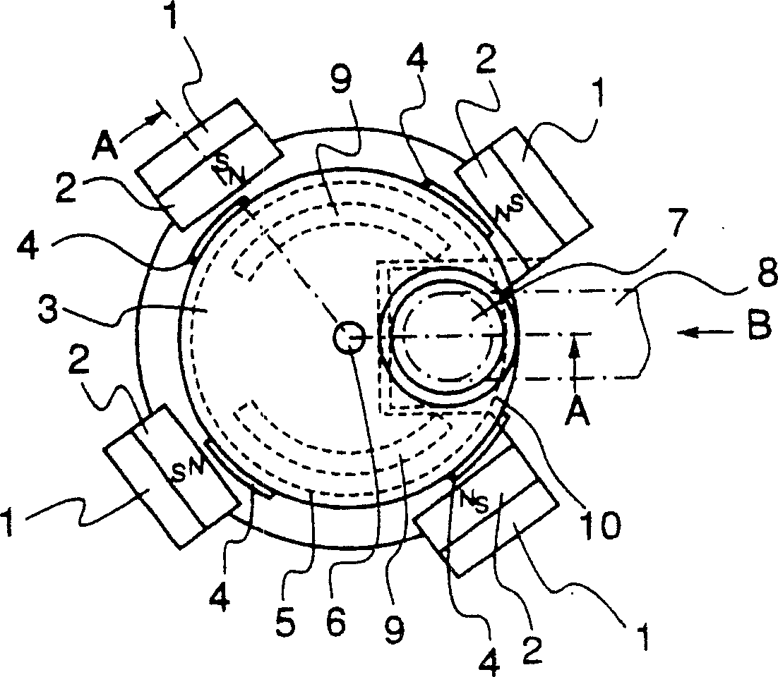
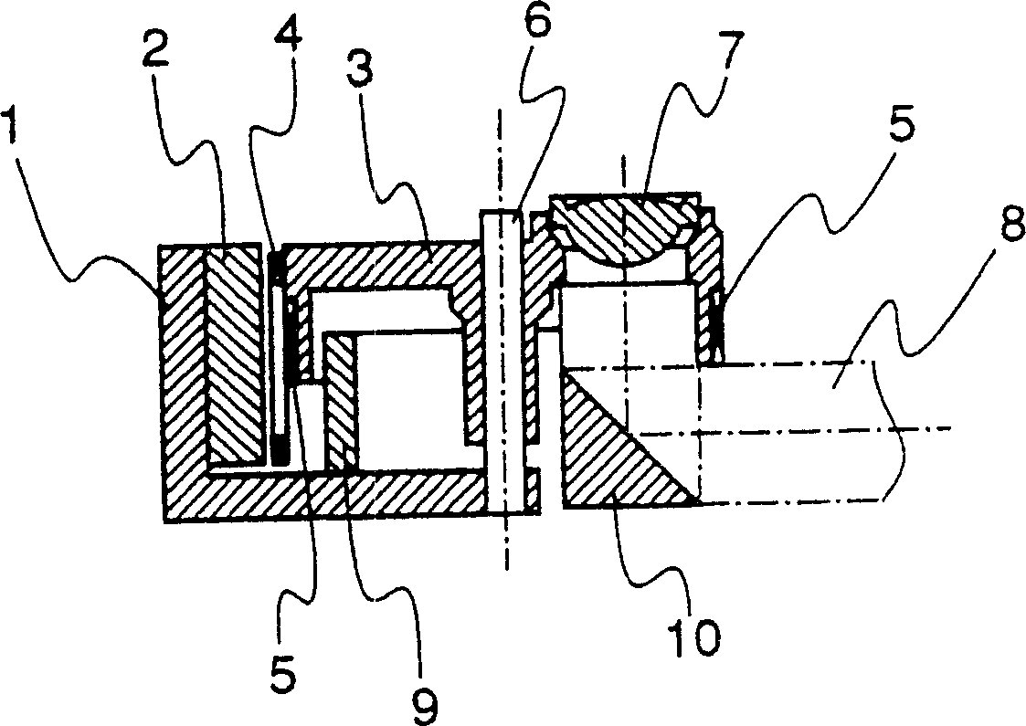
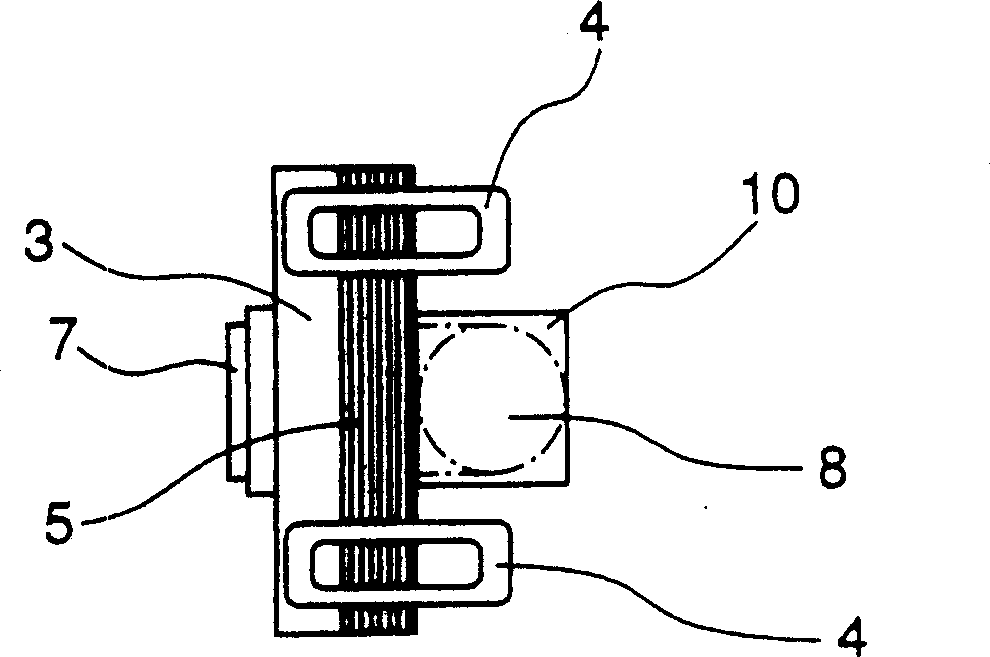
[0053] figure 1 An explanatory diagram showing the structure of the first embodiment of the objective lens driving device of the present invention. figure 2 Means figure 1 A cross-sectional view along the line A-A in the middle. image 3 Means from figure 1 The view of the objective lens driving device when viewed in the direction of arrow B.

[0054] in figure 1 There is an objective lens 7 in the lens holder 3, which is supported and guided by a sliding shaft 6, and the sliding shaft 6 is slidably and rotatably arranged to be substantially parallel to the optical axis direction of the objective lens 7. The focusing coil 5 is wound around the outer circumference of the lens holder 3, and the tracking coil 4 is coaxially arranged on the outer ...


PUM

PropertyMeasurementUnit
radiusaaaaaaaaaa

Abstract

A thin and compact objective lens driving device. Optical beam is passed through a space surrounded by a tracking coil and a focusing coil which are adjacent to each other and fixed in a holder. Position the objective lens with high precision for switching a plurality of objective lenses in accordance with the type of an optical disc. Magnetic substances which are radially extended with the sliding shaft at the center are provided in the lens holder, and the magnetic substances are located within a plane perpendicular to the plane constituting the magnetic gap and at the outside of the magnetic gap. The device prevents the occurrence of positional displacement of the objective lens due to resistance force of current supply means such as FPC. To achieve this object, a first objective lens and a second objective lens are arranged so that the objective lens arrangement angle at which the first and second objective lenses are arranged with respect to the shaft center of the sliding shaft is displaced, by a predetermined amount, from the magnetic circuit arrangement angle at which the magnetic substances and the magnets are arranged with respect to the shaft center of the sliding shaft.

Description

Technical field [0001] The present invention relates to an objective lens driving device and an optical disc device using the objective lens driving device. Background technique [0002] An objective lens driving device used in an optical disc device is disclosed in Japanese Utility Model Application Hei-2-35330. [0003] Picture 9 Shows the structure of the objective lens driving device. Picture 10 Is along the G-G line ( Picture 9 Middle) a cross-sectional view of the objective lens driving device, Picture 11 Is along Picture 9 Schematic diagram in the direction of arrow F. [0004] The objective lens 7 is located in the lens holder 3, and the lens holder is supported and guided by a sliding shaft 6 slidable and rotatable parallel to the optical axis direction of the objective lens 7. A focusing coil 5 is wound on the outer peripheral surface of the lens holder 3, and tracking coils 4 are arranged at a certain interval in the peripheral direction of the outer peripheral p...

Claims


Application Information

Patent Timeline
Patent Type & Authority Patents(China)
IPC IPC(8): G11B7/08G11B7/00G11B7/09G11B7/135
CPCG11B7/093G11B7/0935G11B7/1374G11B2007/0006G11B7/0933G11B7/1362
Inventor 乾真朗落尚彦泉克彦三浦美智雄黑田直光水野隆一郎
Owner HITACHI LTD
Why Eureka
Try Eureka