Fuel injection valve

A fuel injection valve, fuel injection device technology, applied in the direction of fuel injection device, special fuel injection device, charging system, etc., can solve the problems of system temperature fluctuation, high cost, high processing cost, and achieve precise working mode, inclined Small tendencies, easy to produce effects

Inactive Publication Date: 2004-11-10
ROBERT BOSCH GMBH
View PDF2 Cites 0 Cited by
  • Summary
  • Abstract
  • Description
  • Claims
  • Application Information

AI Technical Summary

Problems solved by technology

[0008] Disadvantages of this device are particularly limited in use in systems with large temperature fluctuations
The device known from DE 197 02 066 C2 is not up to the task due to the non-linear behavior of the thermal expansion coefficient of the piezoceramic as a function of the temperature change
The disadvantage of this device is the high processing cost, which makes the cost relatively high, which is mainly related to the choice of material (eg Invar alloy)

Method used


Image

  • Fuel injection valve
  • Fuel injection valve

Examples


Embodiment Construction

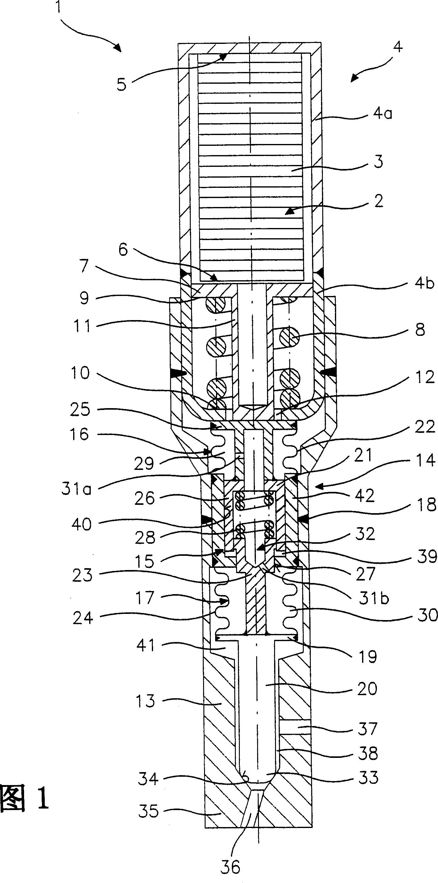
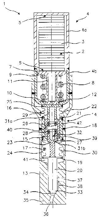
[0026] FIG. 1 shows an exemplary embodiment of a fuel injector 1 according to the invention in an axial sectional view. This is an inwardly opening fuel injector 1 . It is used in particular for the direct injection of fuel into the combustion chamber of a hybrid compression forced ignition internal combustion engine.

[0027] An actuator 2 , which is preferably designed as a disk-shaped piezoelectric or magnetostrictive element 3 , is accommodated in a two-part actuator housing 4 . The actuator 2 is surrounded at a first end face 5 in a sleeve-like manner by a first actuator housing part 4 a with a cover part and rests with a second end face 6 on an actuator flange 7 . A preload spring 8 rests with a first end 9 on the actuator flange 7 and is surrounded by a second actuator housing part 4 b in a sleeve-like manner, the second end 10 of the preload spring 8 It is supported on the second actuator housing part. The two actuator housing parts 4a, 4b are welded together, for e...


PUM


Abstract

The invention relates to a fuel injection valve (1), especially an injection valve for fuel injection systems of internal combustion engines, that comprises a piezoelectric or magnetostrictive actuator (2), a valve closing body (33) which can be actuated by the actuator (2) by means of a valve needle (20) and engages with a valve seat surface (34) to form a sealing seat and a hydraulic lifting device (14) with two lifting pistons (21, 23) that can be moved against each other. The lifting device (14) is a constructional unit which is hermetically sealed against a valve inner chamber (41) and is provided with a housing (15) with at least one section (16, 17) that is flexible in the axial direction.

Description

technical field [0001] The invention relates to a fuel injection valve. Background technique [0002] A fuel injector is known from DE 195 00 706 A1. [0003] The device described in DE 195 00 706 A1, in particular for metering liquids and gases in fuel injection valves for internal combustion engines, has a hydraulic displacement amplifier for converting the adjustment displacement of a piezo actuator to a valve needle magnified itinerary. In order to spatially integrate the displacement amplifier into the valve housing with a small overall size, a diameter-reduced end section is provided on the reciprocating piston of the displacement amplifier, which protrudes into a groove of the working piston of the displacement amplifier. A disc spring attached to the booster chamber bounded by the piston presses the working piston against the actuator, and a helical compression spring arranged concentrically to the end section in the groove presses the reciprocating piston against ...

Claims


Application Information

Patent Timeline
Patent Type & Authority Patents(China)
IPC IPC(8): F02M51/06F02M61/16F02M63/00
CPCF02M2200/16F02M51/0603F02M61/167
Inventor 沃尔夫冈·吕勒胡贝特·斯蒂尔马蒂亚斯·博伊京特·霍尔诺贝特·凯姆
Owner ROBERT BOSCH GMBH
Why Eureka
Try Eureka