Device for providing shutting force for plastic injection machine for shoe manufacture

A technology of injection molding machine and closing force, which is applied in the direction of fluid pressure actuators, mechanical equipment, servo motors, etc., and can solve the problem of large land occupation and other problems

Inactive Publication Date: 2004-12-01
KLOCKNER DESMA SCHUHMASCHEN
View PDF0 Cites 0 Cited by
  • Summary
  • Abstract
  • Description
  • Claims
  • Application Information

AI Technical Summary

Problems solved by technology

In addition to not excluding the risk of loss of hydraulic fluid that may arise as a result, the claimed device requires a relatively large footprint

Method used


Image

  • Device for providing shutting force for plastic injection machine for shoe manufacture
  • Device for providing shutting force for plastic injection machine for shoe manufacture
  • Device for providing shutting force for plastic injection machine for shoe manufacture

Examples


Embodiment Construction

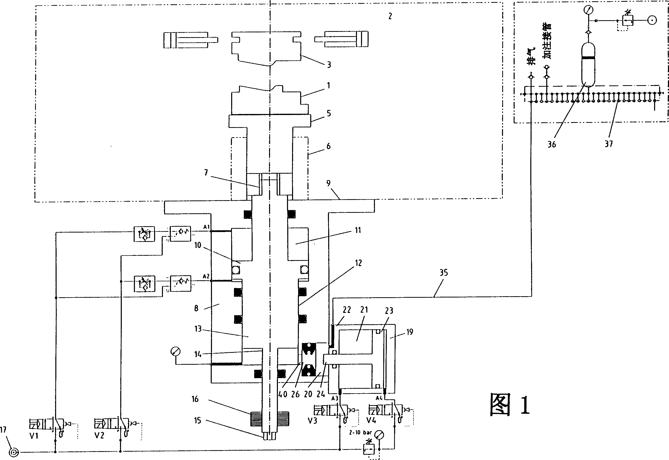
[0020] 1 schematically depicts a drive for the vertical movement of a bottom mold 1 in a forming station 2 on a circular table of an injection molding machine for the manufacture of shoes, not shown. The forming station 2 comprises, in addition to the bottom mold 1 , not shown side mold parts and a displacer 3 . The bottom mold 1 and the ejector 3 and the side molds form a cavity for the manufacture of shoe soles. In this figure the apparatus for producing the outermost layer of the sole is depicted.

[0021] The bottom form 1 is mounted on a lift table 5 which is guided vertically in a lift table guide rail 6 . The piston rod 7 of a first piston-cylinder arrangement, referred to below as the die cylinder 8 , acts on the lifting table 5 from below, which is connected at 9 to the forming station.

[0022] The piston rod 7 is assigned a piston 10 which can be acted on both sides with compressed air via the compressed air lines A1 and A2. With the aid of compressed air, the pi...


PUM


Abstract

Disclosed is a device for applying closing force in injection molding machine in particular for producing shoe and sole. The injection molding machine comprises at least one mold tool for producing the sole to be produced or formed. The mold tool is comprised of a side mold portion, a bottom pressing mold that is vertically movable, and an ejector or a last forming portion, the last being provided with a boot portion and serving to delimit a mold cavity. The force application device comprises a piston-cylinder device (tool base punch cylinder) for moving the tool base punch. The piston-cylinder device comprises two separate chambers, wherein a piston is movable in the chamber. The piston is fed on both sides with compressed air. A second piston is movable in the second chamber. The second piston is fed on one side with a hydraulic pressure medium. The two pistons are securely connected to each other. The hydraulic pressure medium can be driven into the second chamber from a storage tank in communication with the second chamber and flows from the second chamber back into the storage tank by using the pneumatic pressure. The force application device further comprises a force amplifying cylinder to generally apply the closing force.

Description

technical field [0001] The invention relates to a device for applying a closing force to an injection molding machine, in particular for the production of shoes and shoe soles, which device has at least one mold for the shoe sole to be produced or formed, the mold being controlled by a side The module, a vertically movable bottom mold and a displacer or a shoe last related to the upper are formed as the upper mold cavity boundary, with a piston-cylinder device (bottom mold cylinder) for moving the bottom mold, the piston-cylinder device has Two mutually sealed cylinder chambers, in which, in one cylinder chamber, a piston that can be loaded with compressed air on both sides can move, and in the second cylinder chamber, a piston can be loaded with liquid pressure medium on one side. movement, the two pistons are rigidly connected to each other, wherein the liquid pressure medium can be pressed into the second cylinder chamber by means of pneumatic pressure from a storage device...

Claims


Application Information

Patent Timeline
Patent Type & Authority Patents(China)
IPC IPC(8): B29C45/67F15B11/032
CPCF15B2211/216F15B2211/30525B29C45/67F15B2211/30565F15B2211/40584F15B2211/7055F15B11/0325F15B2211/625F15B2211/41527F15B2211/30515F15B2211/775F15B2211/212F15B2211/40515B29C2045/6792
Inventor 鲁道夫·克雷默
Owner KLOCKNER DESMA SCHUHMASCHEN
Why Eureka
Try Eureka