Multi channel imaging engine apparatus

An assembly and projector technology, applied in the direction of image communication, using projection device image reproducer, pulse technology, etc., can solve the problems of difficult adjustment and use, not ideal enough rigidity, difficult cost, etc., to achieve cheap production, adjustment Accurate and use cheap, vibration effect elimination effect

Inactive Publication Date: 2004-12-08
AURORA SYSTEMS INC
View PDF0 Cites 0 Cited by
  • Summary
  • Abstract
  • Description
  • Claims
  • Application Information

AI Technical Summary

Problems solved by technology

[0004] To the best of the inventor's knowledge, all prior apparatus and methods for producing a multi-channel imager have been difficult and / or expensive to manufacture and assemble, less than ideally rigid, and difficult to align and use

Method used


Image

  • Multi channel imaging engine apparatus
  • Multi channel imaging engine apparatus
  • Multi channel imaging engine apparatus

Examples


Embodiment Construction

[0052] The various embodiments and modifications of the invention described herein and / or shown in the drawings are presented by way of example only and do not limit the scope of the invention. Unless specifically stated otherwise, individual aspects and components of the invention may be deleted or modified, or may be replaced by some known equivalent, or some heretofore unknown alternatives, such as may be developed in the future or such as may be Substitutions found to be acceptable alternatives. The invention can also be modified for use in a wide variety of applications while remaining within the spirit and scope of the claimed invention, since the range of potential applications is vast, and since the invention is intended to be amenable to many such variations.

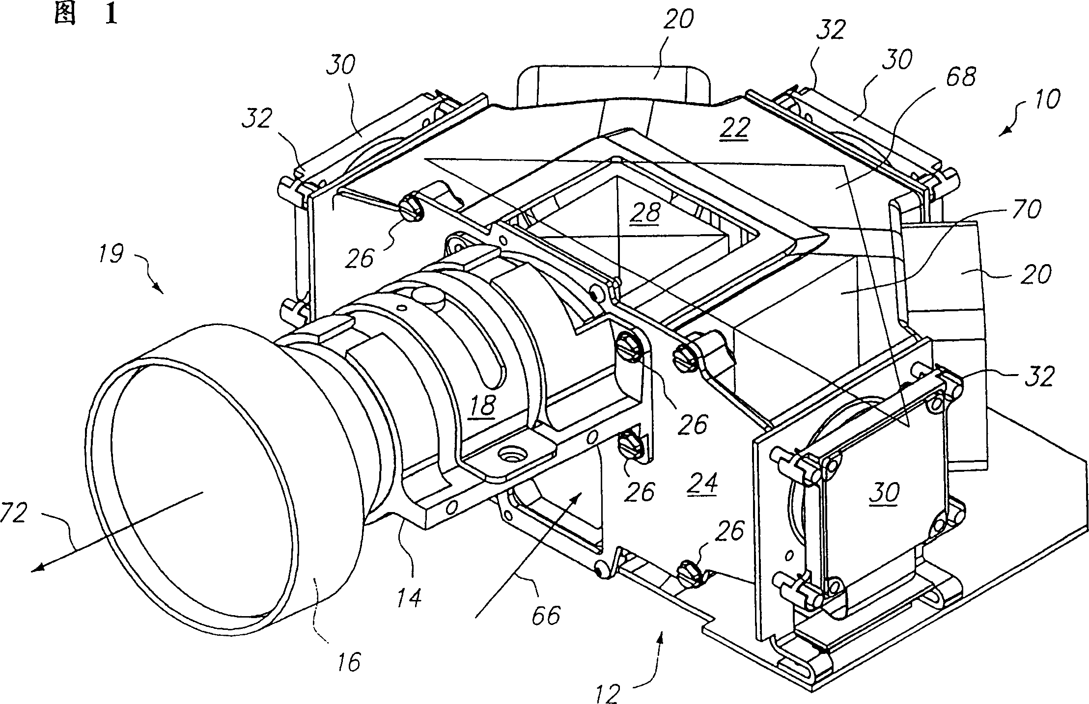
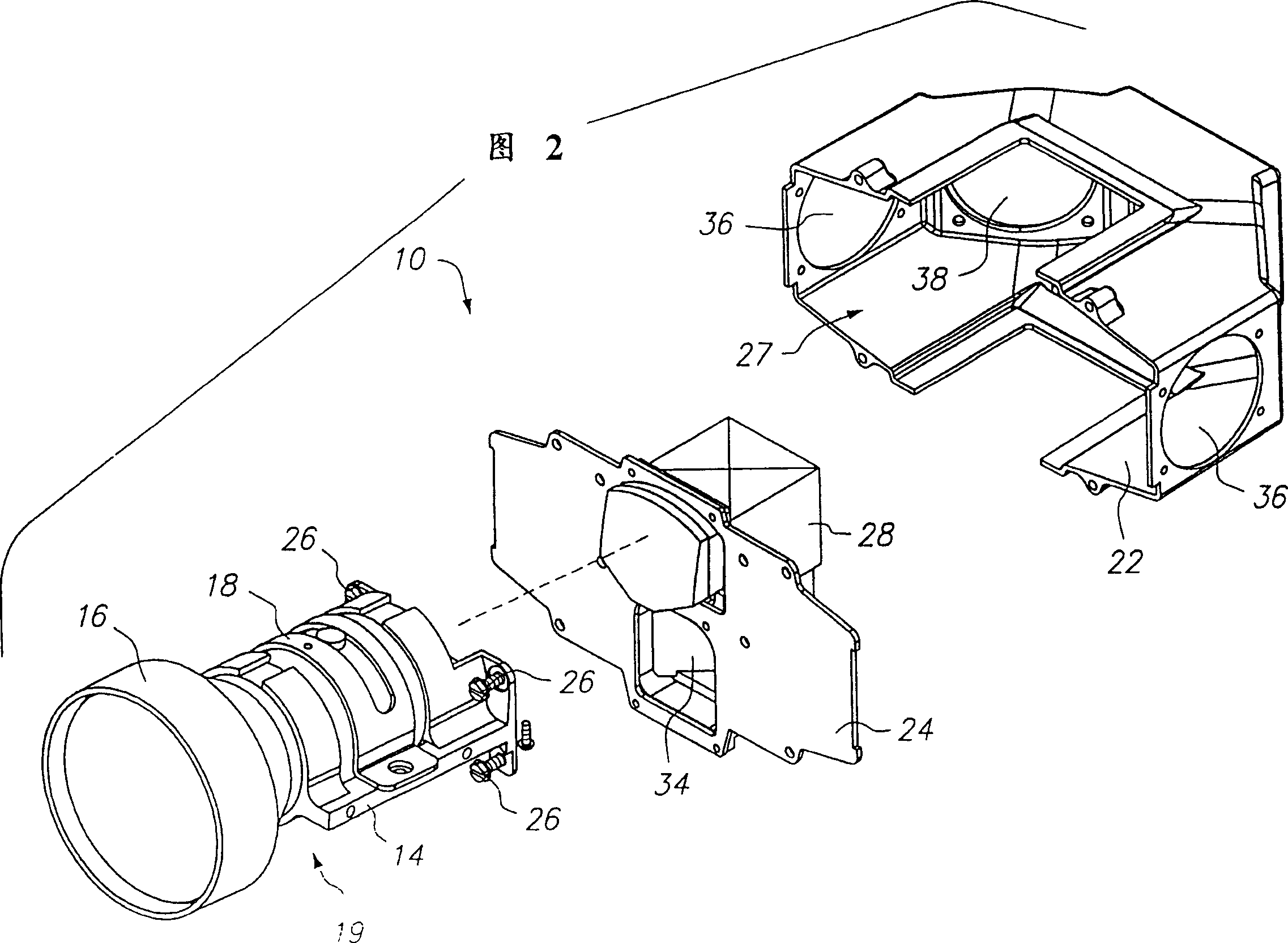
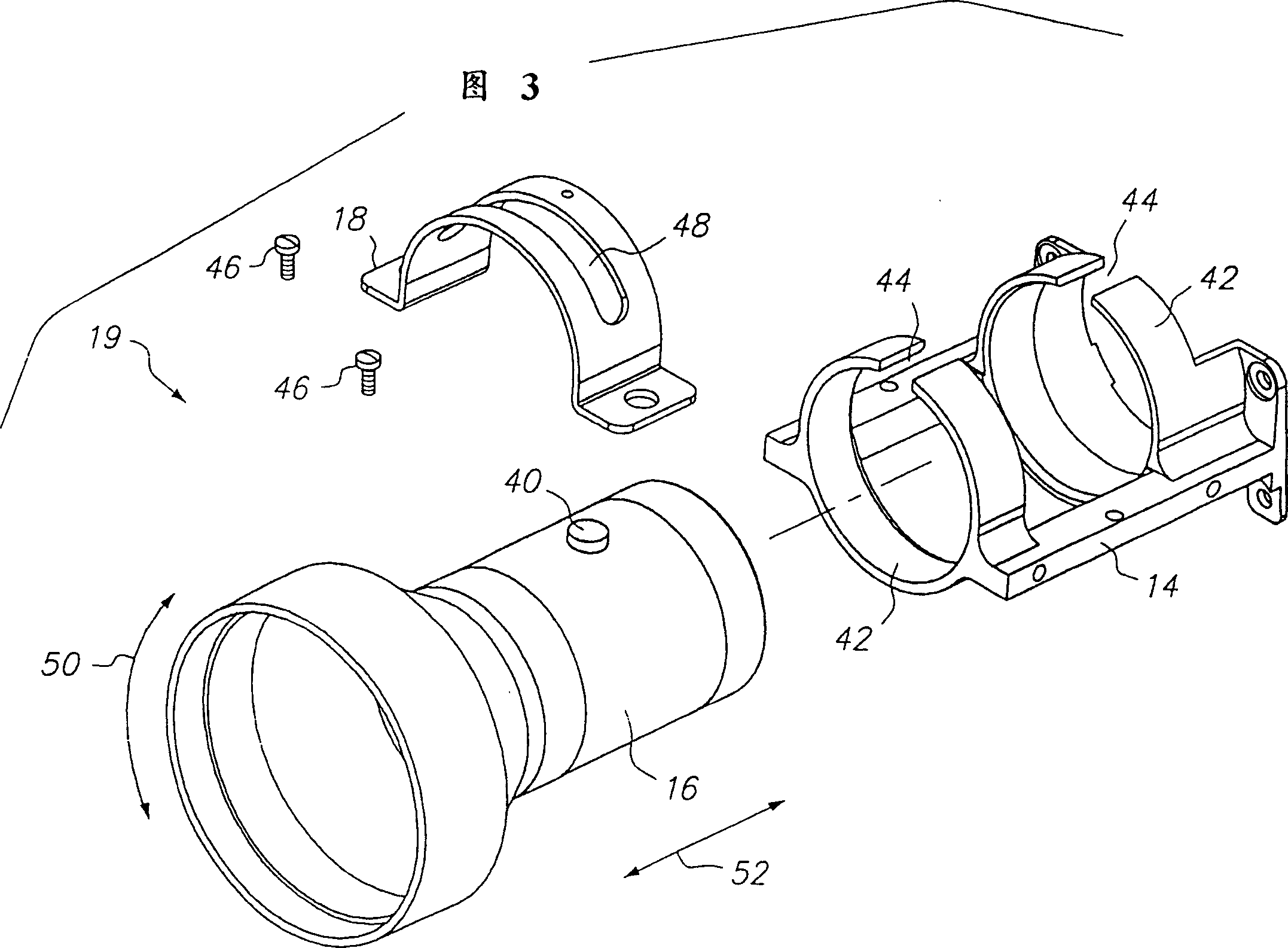
[0053]As described herein, the mode of carrying out the invention is a multi-channel imaging machine. An example of a multi-channel imaging machine of the present invention is depicted in a perspective view in...


PUM


Abstract

A multi channel video engine (10) for accepting, dividing, modifying and recombining light to project an image. A housing (12) encloses an optical assembly (28) having a dichroic mirror assembly (58) and a color cube (60). A plurality of LCD assemblies accept light from the dichroic mirror assembly (58), modifies it, and reflects it to the color cube (60). A lens assembly (16) is affixed to a bulkhead (24) of the housing (12) using a lens cradle (14) and lens retainer (18). An output prism (54) aligns light onto a second plane (70) to coincide with an optical axis (72) of the lens assembly (16).

Description

technical field [0001] The present invention relates to multi-channel imaging devices, and more particularly to projection-type imaging devices, where it is very important to precisely align the actual components of the device so that the individual components of a resulting image The color components will be tuned. The present primary application of the multi-channel imager of the present invention is as a component of a projection video display device where it is desirable to have a robust and precisely aligned opto-electronic arrangement for projecting well aligned color image. Background technique [0002] A typical configuration for a multi-channel imaging system will have a clamshell configuration where the internal optics and components are assembled from above and the optical cavity is split in half along a horizontal plane. However, the construction of such a device results in two or more planes of assembly. For example, at least one is horizontal for housing sep...

Claims


Application Information

Patent Timeline
Patent Type & Authority Patents(China)
IPC IPC(8): H04N5/74H04N9/31
CPCH04N9/3197H04N9/3144H04N9/317H04N9/3141
Inventor 琼-皮埃尔·梅纳德
Owner AURORA SYSTEMS INC
Why Eureka
Try Eureka