
Method for making optical fiber beam bunching array

A manufacturing method and fiber bundle technology, applied in the field of optoelectronics, can solve the problems of low tensile strength and mechanical strength, complex process, large angular error of optical fiber array, etc.

Inactive Publication Date: 2005-01-26
INST OF SEMICONDUCTORS - CHINESE ACAD OF SCI
View PDF0 Cites 0 Cited by
  • Summary
  • Abstract
  • Description
  • Claims
  • Application Information

AI Technical Summary

Problems solved by technology

There are two disadvantages in applying these two methods to manufacture optical fiber bundle line arrays: first, the substrate of each optical fiber bundle array needs to have optical fiber positioning grooves or optical fiber positioning holes, so the cost is high and the process is complicated; the second , what is glued and fixed in the groove or hole is the bare cladding optical fiber with the coating removed, so the tensile strength and mechanical strength of the optical fiber bundle line array are very small, and the optical fiber is extremely easy to break during operation and use
In addition, in the second method, due to the thickness of the substrate, the angular error of the obtained optical fiber array is relatively large

Method used


Image

  • Method for making optical fiber beam bunching array
  • Method for making optical fiber beam bunching array
  • Method for making optical fiber beam bunching array

Examples


Embodiment Construction

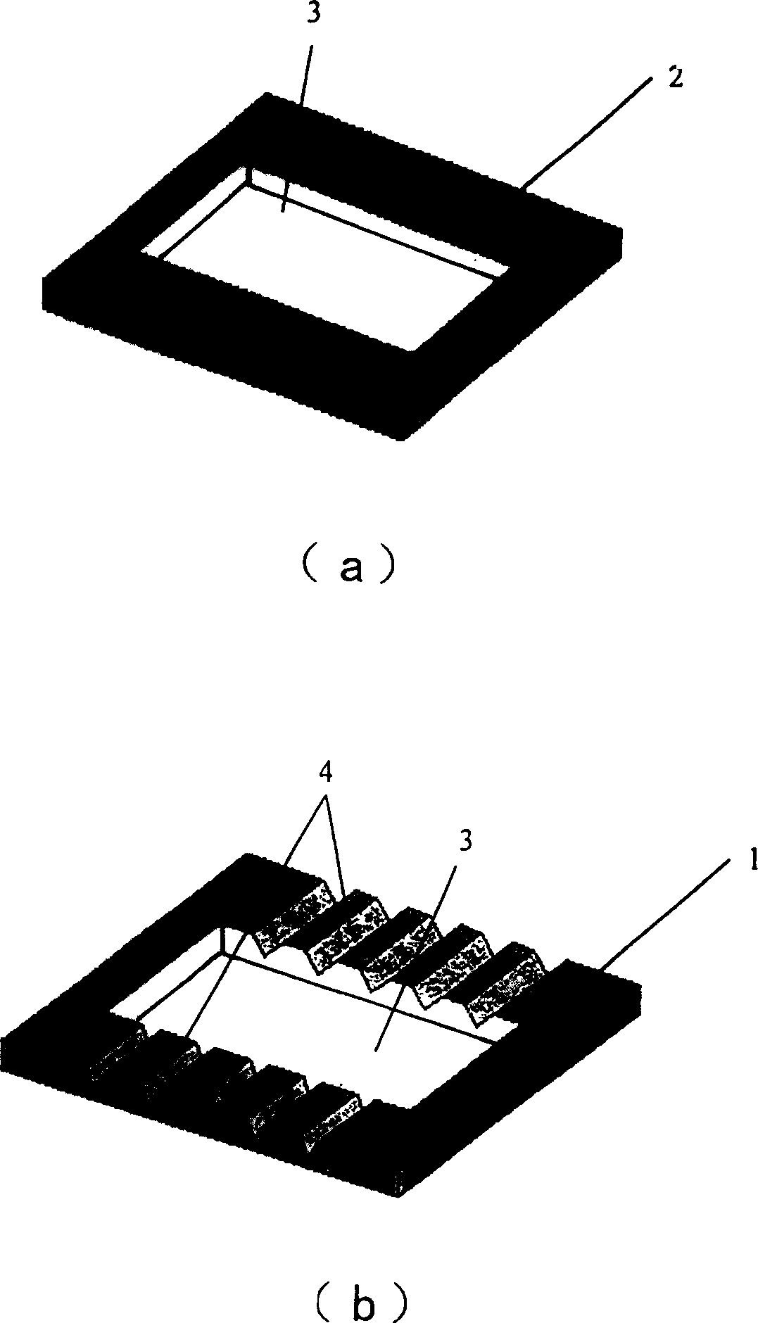
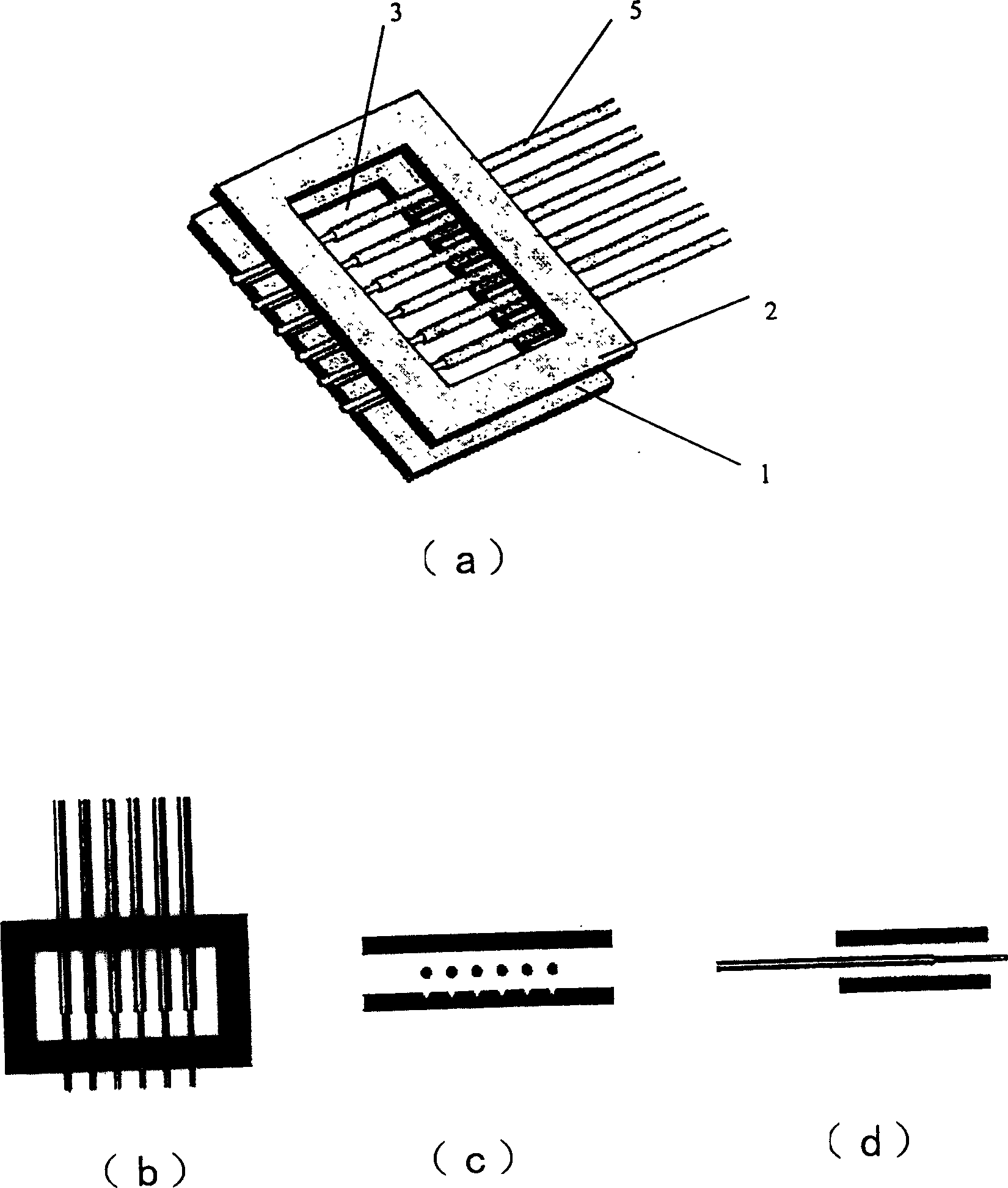
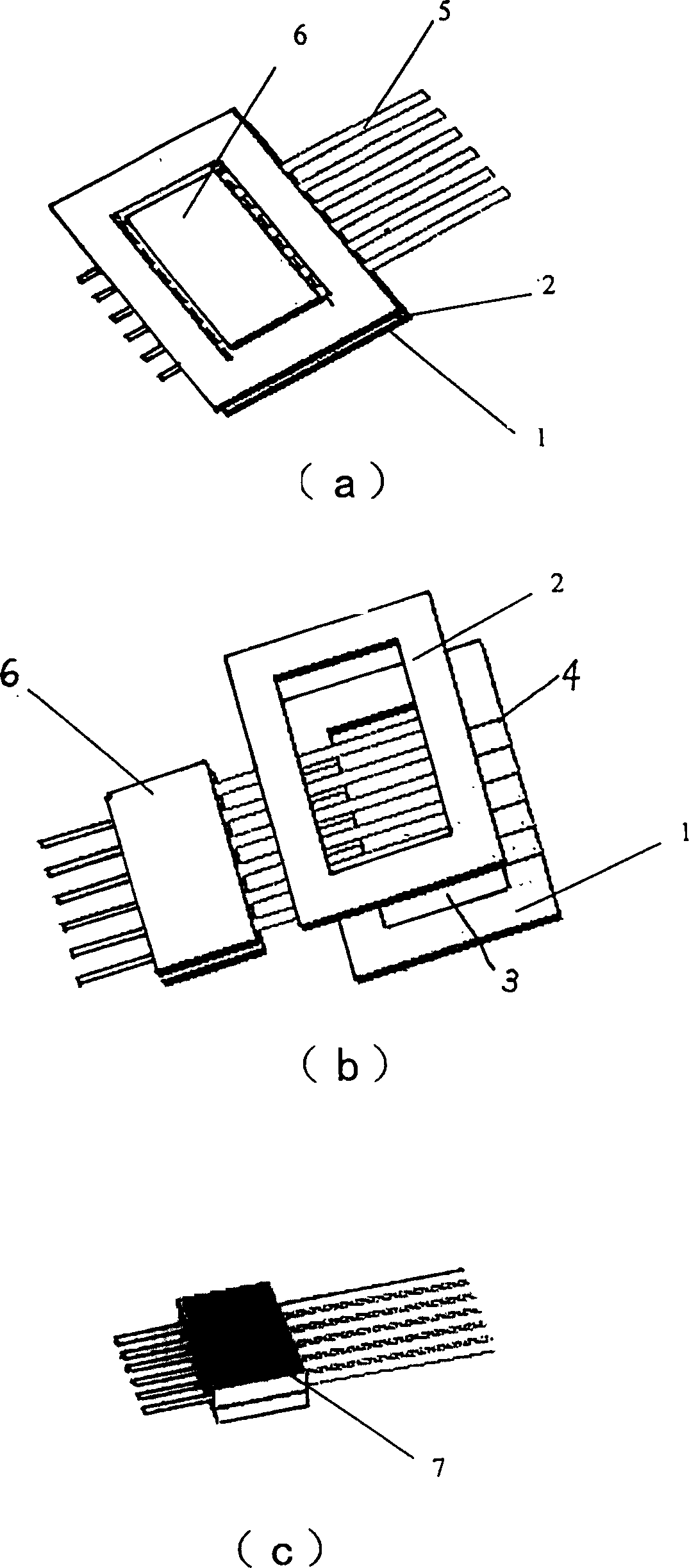
[0022] see image 3 , and see in conjunction with figure 1 and figure 2 , a manufacturing method of an optical fiber bundle line array of the present invention is characterized in that: it comprises the following steps:

[0023] 1) Make an optical fiber embedding substrate 1, the optical fiber embedding substrate 1 is rectangular and has a rectangular square hole 3 in the middle. The optical fiber positioning groove 4 for fixing the optical fiber, the optical fiber positioning groove 4 is wide at one end and narrow at the other end, and can accommodate the thick end and the thin end of the optical fiber 5 respectively (the thick end is the part with the coating layer, and the thin end is the part with the coating layer removed. the bare fiber part);

[0024] 2) Make a cover plate 2, the cover plate 2 has the same shape as the optical fiber embedded substrate 1, also has a rectangular square hole 3 in the middle, the rectangular square hole 3 can also be circular or other s...


PUM


Abstract

The present invention discloses a method for making optical fiber beam bunching array which comprises, producing an optical fiber embed substrate, making a cover plate having the same shape as the optical fiber imbed substrate, placing the optical fiber into the optical fiber locating slot on the optical fiber embed substrate in turn, covering the cover plate and mounting, taking two substrates having the same shape as the rectangular square hole of the optical fiber imbed substrate, sticking by bonding the two substrates and the optical fiber, disconnecting the optical fiber imbed substrate and the cover plate, thus forming the optical-fiber beams array.

Description

technical field [0001] The invention belongs to the technical field of optoelectronics, and relates to an optical element and a manufacturing process thereof, in particular to a manufacturing method of an optical fiber bundle line array. Background technique [0002] In medical treatment, pumping, material processing and processing, etc., greater fiber-coupled output power of semiconductor lasers is required, and an effective way to increase the fiber-coupled output power of semiconductor lasers is to use a one-dimensional fiber bundle line array to realize high-power semiconductor lasers. Fiber-coupled output of laser bar array. In addition, due to the sharp increase of broadband and high-speed communication services, it is necessary to arrange multiple optical fibers into an array of optical fiber bundles as input and output interfaces. Therefore, as an optical component, the fiber bundle line array is used more and more widely. [0003] Currently, two methods are common...

Claims


Application Information

Patent Timeline
Patent Type & Authority Patents(China)
IPC IPC(8): G02B6/08G02B6/13
Inventor 王晓薇马骁宇肖建伟方高瞻
Owner INST OF SEMICONDUCTORS - CHINESE ACAD OF SCI
Learn More