Bonding pad of suspension circuit

A pad and electrical technology, applied in the direction of assembling printed circuits with electrical components, welding media, welding equipment, etc., can solve problems such as increasing production process time and damage to magnetic head components

Inactive Publication Date: 2005-02-09
SAE MAGNETICS (HK) LTD
View PDF0 Cites 0 Cited by
  • Summary
  • Abstract
  • Description
  • Claims
  • Application Information

AI Technical Summary

Problems solved by technology

This process increases the production process time
Also, as mentioned above, the manufacturing of the magnetic head assembly goes through many processes, so the magnetic head assembly may be damaged by static electricity during handling

Method used


Image

  • Bonding pad of suspension circuit
  • Bonding pad of suspension circuit
  • Bonding pad of suspension circuit

Examples


Embodiment Construction

[0025] Preferred embodiments of the present invention will now be described in detail with reference to the accompanying drawings.

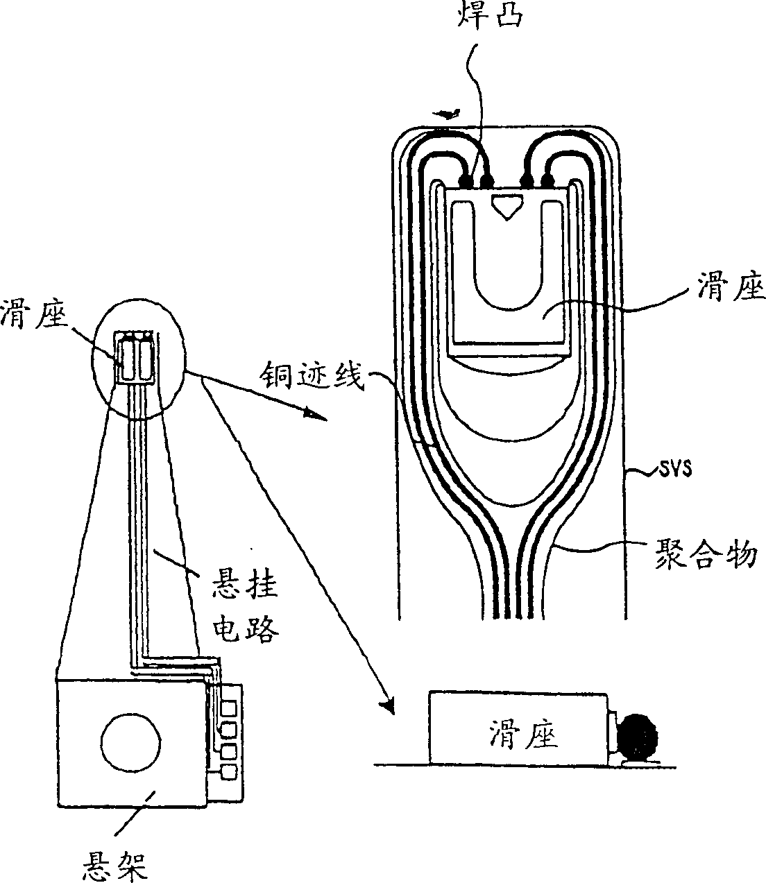
[0026] figure 1 are examples of magnetic recording heads and suspension circuits,

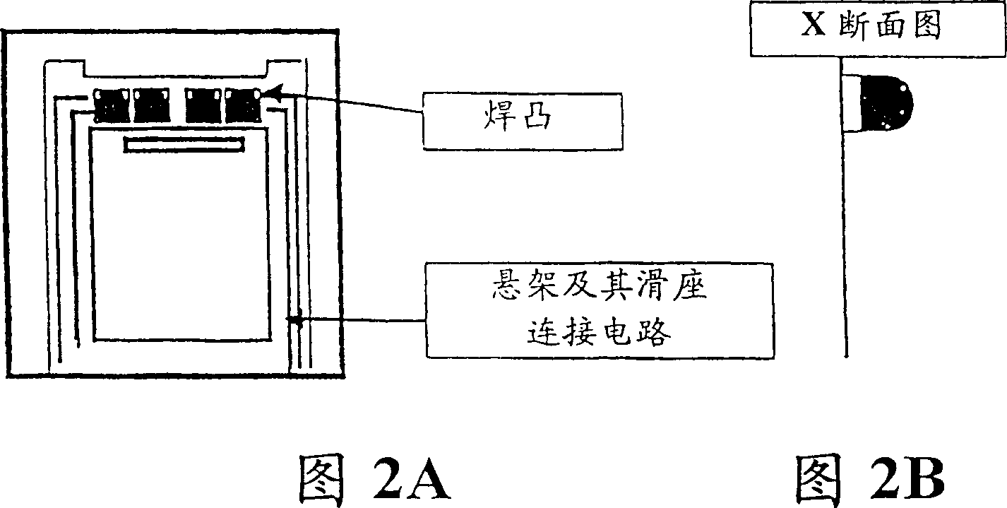
[0027] FIG. 2A is a top view of a pad of a suspension circuit. As shown in the figure, there are several soldering points at one end of the suspension, which are used to weld the suspension to its slider connection circuit. Solder joints include conductive metals and surface treatments such as solders, conductive polymers, adhesives and films.

[0028] FIG. 2B is a cross-sectional view of pads of the suspension circuit shown in FIG. 2A. As shown in Figures 2A and 2B, the solder joints are cylindrical and semicircular, with a height of approximately 50-300 microns and a diameter of less than 180 microns.

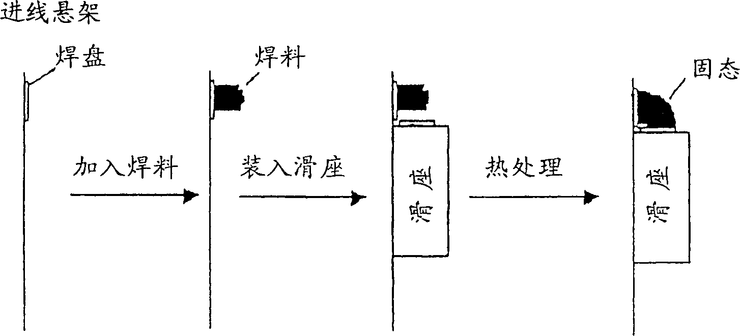
[0029] refer to image 3 , which is a flowchart illustrating the assembling method of the present invention, at first, the metal sheet is set on the suspens...


PUM

PropertyMeasurementUnit
diameteraaaaaaaaaa
heightaaaaaaaaaa

Abstract

A new type of suspension circuit electrical bonding pad is described for electrically and mechanically connecting process for the magnetic recording head. The new type of bonding pad will serve as the joint material as well as the joint interface. Thus there is no need to apply the conductive material in between the bonding pads and magnetic recording head terminals, consequently reducing the process leading time and simplifying the magnetic recording head assemble process.

Description

technical field [0001] Field of the Invention This invention relates generally to circuit pads for magnetic recording heads of disk drives and, more particularly, to circuitry and suspension assemblies for magnetic head assemblies of disk drives. Background technique [0002] Generally, a magnetic head assembly is constructed such that a head slider having a magnetic head element is supported by a slider suspension (hereinafter referred to as a suspension). When the head slider is suspended by a suspension at a fixed distance from the surface of the magnetic recording medium, information is reproduced from the recording medium such as a magnetic disk, or information is recorded on the recording medium. [0003] The following general disclosure seems to be relevant to the present invention: Japanese Laid-Open Patent Publication No.Sho63-226999 discloses a flexible shielded wire circuit board, its structure is that an anisotropic conductive sheet is welded to an insulating sub...

Claims


Application Information

Patent Timeline
Patent Type & Authority Patents(China)
IPC IPC(8): B23K35/12G11B5/127G11B5/48G11B5/60G11B15/64G11B17/32G11B21/08H05K3/34
CPCG11B5/4853G11B5/4826Y10T29/49169Y10T29/49025Y10T29/49144
Inventor 王晓明陶峰
Owner SAE MAGNETICS (HK) LTD
Why Eureka
Try Eureka