Electric lamp

A technology for electric lamps and lamp caps, applied in discharge lamps, circuits, incandescent lamps, etc., can solve problems such as troublesome, difficult processes, and the risk of short circuits due to high distance between current conductors, reducing the risk of electrical contact disconnection and simplifying assembly. The effect of craftsmanship

Inactive Publication Date: 2005-02-09
KONINKLIJKE PHILIPS ELECTRONICS NV
View PDF1 Cites 0 Cited by
  • Summary
  • Abstract
  • Description
  • Claims
  • Application Information

AI Technical Summary

Problems solved by technology

A disadvantage of the known lamp is that the making of the electrical contact between the current conductor and the contact of the lamp cap by welding or welding involves a rather cumbersome and difficult process
As a result, the known lamp has the additional disadvantage of a rather high risk of short circuits due to the fact that the current conductors are too close to each other or even touch each other due to their undesired bending

Method used


Image

  • Electric lamp
  • Electric lamp
  • Electric lamp

Examples


Embodiment Construction

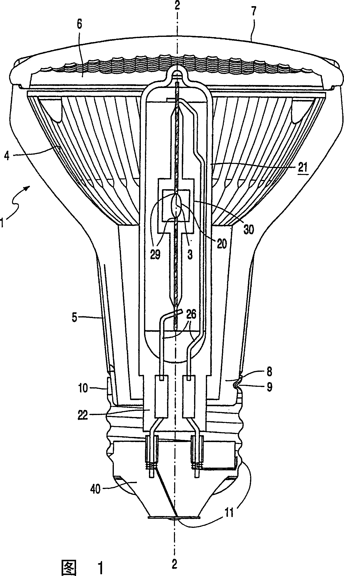
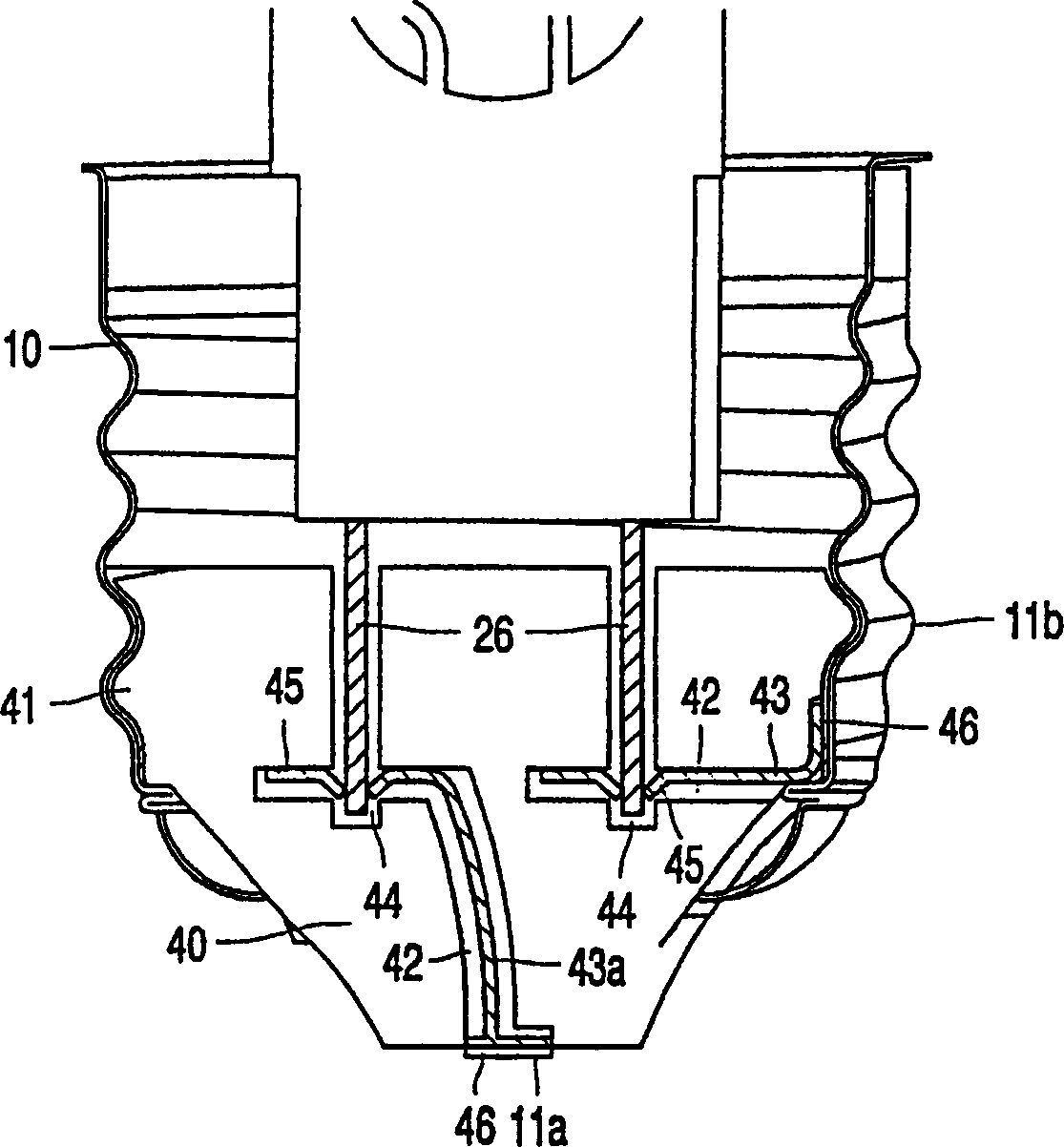
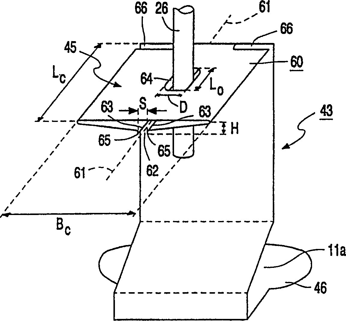
[0027] In Fig. 1 the electric lamp is a reflector lamp having a bulb 1 of light-transmitting material, in this case molded glass, which is partially reflective inside. The reflector thus obtained has a concave light focusing portion 4 , axis 2 and optical center point 3 between the neck 5 and the light emission window 6 . The reflective part of the reflector can be a metal layer, for example made of silver or aluminum, or optionally an interference filter. The light focusing part is a parabolic rotating body that rotates around the axis, and its focal point is at the optical center point. In the figure, the light-transmitting glass cover 7 is fixed to the reflector by means of epoxy resin, thus closing the light emission window 6 . A lamp cap 10 provided with contacts 11 is fixed around the free end 8 of the neck, wherein the lamp cap has been retracted into the recess 9 . Furthermore, the lamp head can also be fixed by means of an adhesive, such as glue. The light source 2...


PUM


Abstract

The electric lamp has a light source (20) in an envelope (21). The light source (20) is secured in a body (1) by means of an insulator body (40) in which current connectors (43) are integrated and which is present in a socket (10) of the reflector lamp. The socket (10) is mechanically connected to the neck portion (5) of the body (1). The integrated insulator/current connector body (40, 43) enables electrical contacting, fixation, and mechanical adjustment of the light source (20) in the body (1). For reliable electrical contacting, the current connector (43) comprises a cylindrical part (60) with scraping edges (63).

Description

technical field [0001] The invention relates to an electric lamp comprising: [0002] Tube and light source with neck; [0003] provided with a contact lamp cap fixed around the free end of the neck; and [0004] A current conductor that passes from the light source through the free end of the neck and is electrically connected to the contacts of the lamp cap. Background technique [0005] Such an electric lamp is known from EP-0758486. Known lamps are reflector lamps with light emission windows, the interior of the bulb being partly reflective. The light source placed inside the bulb of the known lamp is mechanically sealed on the plate. The plate and bulb are secured to the neck of the envelope by means of glue. The current conductor, which passes through the free end of the neck, protrudes into the hollow lamp cap. The lamp cap has a threaded contact around the shaft and a central electrical contact on the shaft. The current conductors of the light source are flexi...

Claims


Application Information

Patent Timeline
Patent Type & Authority Patents(China)
IPC IPC(8): F21S2/00F21Y101/00H01J5/50H01J5/54H01J61/34H01K1/46
CPCH01J61/34H01J5/54
Inventor G·M·卡伦G·N·M·维斯帕格特
Owner KONINKLIJKE PHILIPS ELECTRONICS NV
Why Eureka
Try Eureka