Electric motor rotor and its producing method

A technology for electric motors and rotors, applied in the field of producing said rotors, can solve problems such as inconsistencies

Inactive Publication Date: 2005-02-23
EMPRESA BRASILEIRA DE COMPRESSORES SA (EMBRACO)
View PDF0 Cites 0 Cited by
  • Summary
  • Abstract
  • Description
  • Claims
  • Application Information

AI Technical Summary

Problems solved by technology

[0006] Although this known construction for metal laminations is suitable for mass production, easier to realize, low cost and produces high reliability products,

Method used


Image

  • Electric motor rotor and its producing method
  • Electric motor rotor and its producing method
  • Electric motor rotor and its producing method

Examples


Embodiment Construction

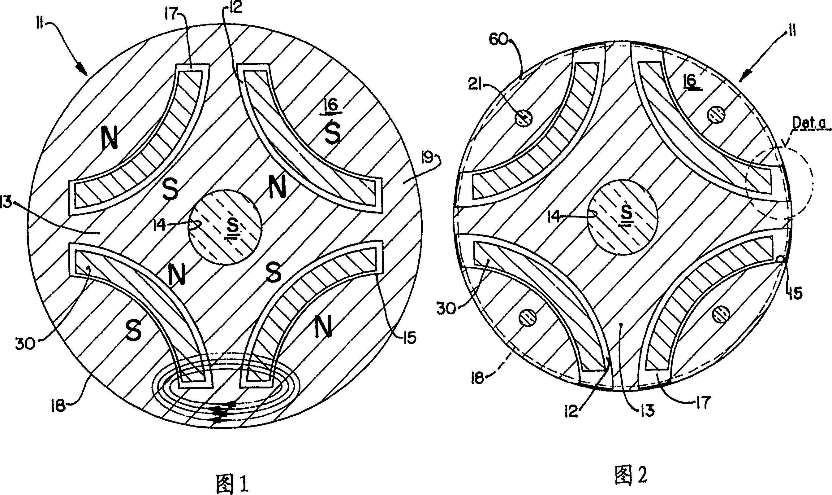
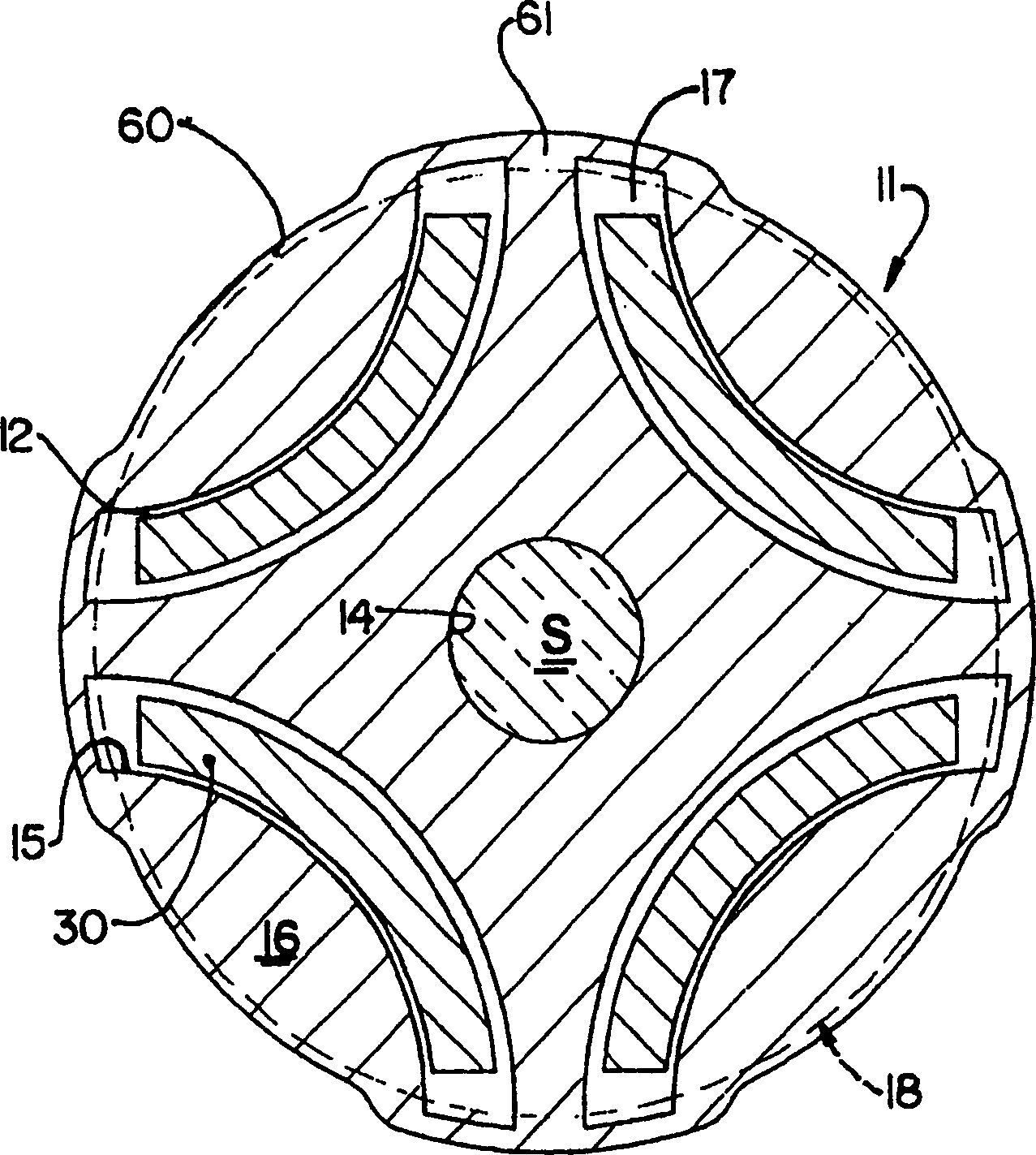
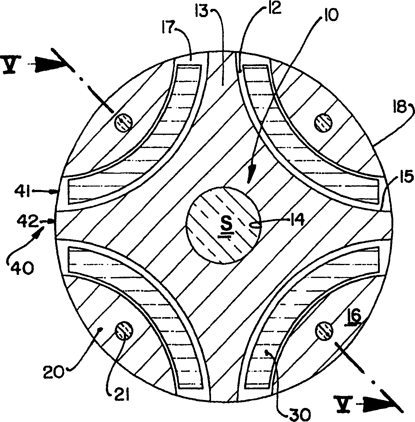
[0019] According to the drawings, the motor rotor of the present invention comprises: a core 10 defined by a plurality of metal laminations 11 of magnetic material such as steel, having a defined electrical conductivity and a defined magnetic permeability, and mutually concentric and overlapping, forming the stack of laminations to be fixed around the extension of the motor shaft S; and the polar peripheral portion 20, fixed around the core 10. Between each said polar peripheral portion 20 and the core 10 is defined an axial housing 12 which occupies the entire longitudinal extension of the rotor and in which a corresponding magnet element 30 is held, said magnet generally having In the form of longitudinal plates, they are for example curved (or rectangular) and arranged according to the same circumferential alignment and spaced from each other.

[0020] According to the prior art, each metal lamination 11 has a central portion 13 provided with: a central opening 14 for mount...


PUM


Abstract

An electric motor rotor and a method for producing an electric motor rotor, said rotor comprising: a core (10), formed by a plurality of metallic laminations (11) of a magnetic material; polar peripheral portions (20) made of a magnetic material and affixed around the core (10); and an equal number of magnet elements (30) retained between the polar peripheral portions (20) and the core (10), the rotor having its cylindrical lateral surface defined by the polar peripheral portions (20), which are circumferentially spaced from each other, and by intermediate peripheral portions (40) provided between each two adjacent polar peripheral portions (20) and having throughout their longitudinal extensions reduced electrical conductibility and reduced magnetic permeability in relation to the core (10), at least in the regions connecting two adjacent polar peripheral portions (20). The rotor further comprises a pair of end caps (50) for retaining the polar peripheral portions (20) to the core (10).

Description

technical field [0001] The invention relates to the construction of a rotor for a brushless electric motor and to a method for producing said rotor with magnet elements arranged inner circumferentially and spaced radially from the side surface of the rotor. Background technique [0002] In the construction of the brushless motor rotor, permanent magnet elements are fixed to the iron core of said rotor so as to be concentrically mounted around the motor shaft. In this configuration, the rotor is formed from a plurality of overlapping metal laminations in longitudinal alignment defining a lamination pack, each metal lamination having a plurality of circumferential pairs equidistant from each other and at an angle to the motor shaft. The windows are aligned with the corresponding windows of the other metal laminations of the stack so as to define an axial housing in which the magnet elements are mounted and fixed. [0003] In prior art constructions, each metal lamination of t...

Claims


Application Information

Patent Timeline
IPC IPC(8): H02K1/22H02K1/27
CPCH02K1/2766Y10T29/49012
Inventor 马可斯·罗谬·墨比尤斯路易滋·泛·道考纳尔克劳迪欧·渥讷·德·利马
Owner EMPRESA BRASILEIRA DE COMPRESSORES SA (EMBRACO)
Why Eureka
Try Eureka