Combined catalysis reactor

A catalytic reactor, reactor technology, applied in combinatorial chemistry, chemical/physical/physical chemistry stationary reactors, chemical instruments and methods, etc., can solve problems such as no indication of catalyst selectivity

Inactive Publication Date: 2005-04-27
UOP LLC
View PDF12 Cites 1 Cited by
  • Summary
  • Abstract
  • Description
  • Claims
  • Application Information

AI Technical Summary

Problems solved by technology

Thermal imaging can be a tool to learn some semi-quantitative information about catal

Method used


Image

  • Combined catalysis reactor
  • Combined catalysis reactor
  • Combined catalysis reactor

Examples


Embodiment Construction

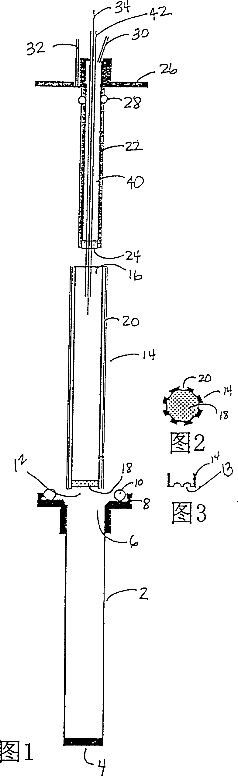
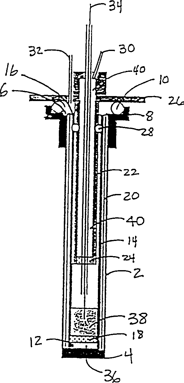
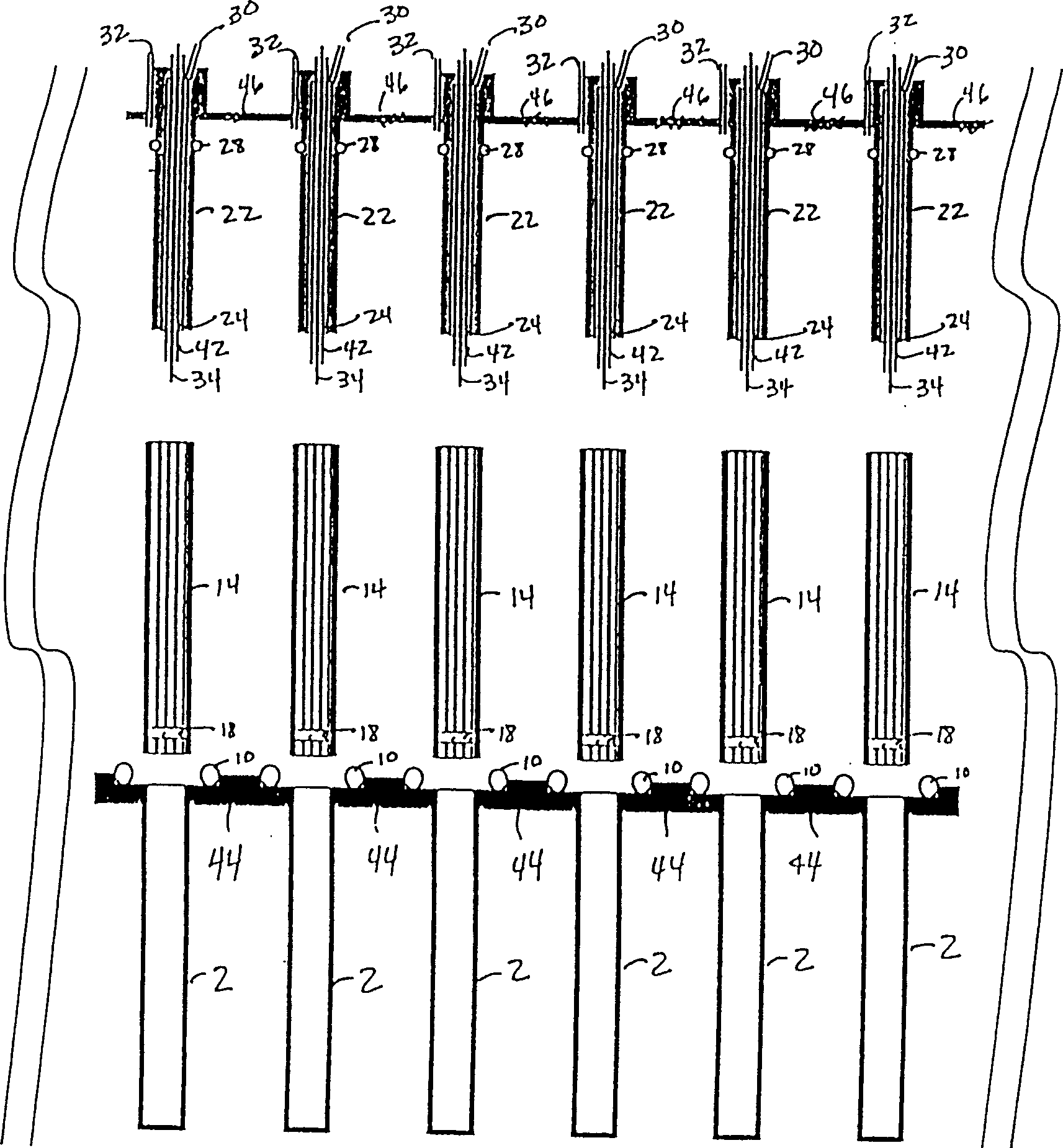
[0016] In general, the present invention is a reactor for combined applications and a method for performing combined catalytic reactions. In a combined application, such a reactor of the present invention is used as an array of multiple reactors operating in parallel at the same time. Preferred such reactors consist of three main components, (1) a top or reactor insert, (2) a vessel or sleeve, and (3) a bottom or shaft. Each of the major components can be fabricated from materials suitable for the application under the intended conditions. Materials are selected to withstand the temperature, pressure and chemical compounds of the specific application. Examples of applicable materials include metals and their alloys, low-grade steels and stainless steels, superalloys such as Incolloy, Inconel, Inconel ( hastalloy), engineering plastics and high temperature plastics, ceramics such as emery and silicon nitride, glass, and quartz, etc.

[0017] In a preferred assembly, the open...


PUM


Abstract

A reactor for conducting catalytic chemical reactions has been developed. T he reactor has a well having an open end and a closed end. The reactor also has a sleeve having a top end and a bottom end. The bottom end of the sleeve is inserted within the open end of the well. A fluid permeable structure is attached to the sleeve spanning the cross-section thereby defining a chamber between the closed end of the well and the fluid permeable structure. The reactor also has a reactor insert having a fluid permeable end and a top end containing a first and a second fluid conduit. The fluid permeable end of the reactor is inserted within the open end of the sleeve. The first fluid conduit is in fluid communication with the chamber, and the second fluid conduit is in fluid communication with the fluid permeable end of the reactor insert.

Description

technical field [0001] The present invention relates to reaction equipment, in particular to combined reactors. Background technique [0002] The development of combinatorial chemistry has mainly focused on the synthesis of chemical compounds. For example, US-A-5612002 and US-A-5766556 disclose methods and apparatus for the multiple simultaneous synthesis of a compound. WO97 / 30784-A1 discloses a microreactor for the synthesis of chemical compounds. Akporiaye, D.E.; Dahl, l.M.; Karlsson, A.; Wendelbo, R.Angew Chem.Int.Ed. -A1, other examples include US-A-5609826, US-A-5792431, US-A-5746982, and US-A-5785927, and WO96 / 11878-A1. [0003] More recently, combinatorial approaches have been applied to catalyst testing in an attempt to speed up the testing process. For example, WO 97 / 32208-A1 teaches that different catalysts are placed in a multi-unit vessel, by observing the release and absorption of heat during the reaction using the corresponding formula and / or analyzing the ...

Claims


Application Information

Patent Timeline
IPC IPC(8): B01J8/00B01J19/00G01N37/00B01J19/24B01J35/00B01J37/00C40B30/08C40B40/18C40B60/12C40B60/14G01N31/10
CPCB01J2219/00702G01N31/10B01J2219/00585B01J2219/00286B01J35/0006B01J2219/00745B01J2219/00423B01J2219/00698C40B60/14B01J2219/00351B01J19/0046B01J2219/00283B01J2219/00299C40B40/18B01J2219/00495C40B30/08B01J2219/00308B01J2219/00747
Inventor I·M·戴尔A·卡尔森D·E·阿科博利亚耶K·M·范登布舍G·P·陶勒R·温德尔布
Owner UOP LLC
Why Eureka
Try Eureka