Image processing method for conference television system

An image processing and video conference technology, applied in the field of multimedia video communication, which can solve the problems that the lower-level clocks cannot be well synchronized, the terminal image is frozen, and the clocks cannot be strictly synchronized.

Inactive Publication Date: 2005-04-27
HUAWEI TECH CO LTD
View PDF0 Cites 0 Cited by
  • Summary
  • Abstract
  • Description
  • Claims
  • Application Information

AI Technical Summary

Problems solved by technology

However, in practical applications, due to the fact that the clocks between the B channels are not strictly synchronized, the lower-level clocks cannot be well synchronized with the upper-level clocks, the switch resets the port, and the trunk circuit is switched, etc., the relative delay between the B channels is caused. It changes again (we call it slip code), but the MCU and the terminal are still adjusted according to the relative delay value calculated for the first time, which makes the receiver unable to extract accurate video bit stream, HMLP and other data , from the phenomenon point of view is the solidification of the terminal image

Method used


Image

  • Image processing method for conference television system
  • Image processing method for conference television system

Examples


Embodiment Construction

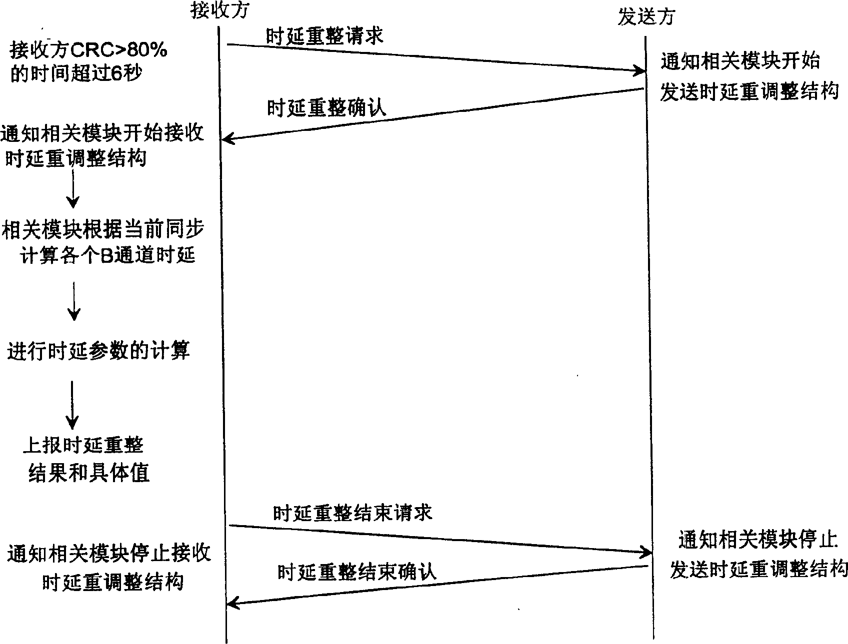
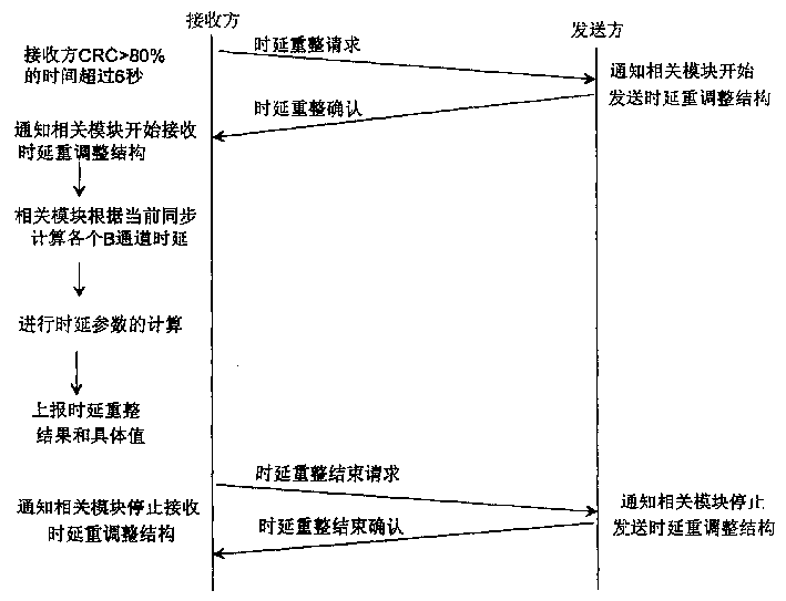
[0013] Combine below figure 1 , specifically describe the image processing method in the video conferencing system of the present invention. The receiver monitors the line CRC (Cyclic Redundancy Check) in real time. When the CRC is greater than 80% for more than 6s, it considers that there is a code slip and sends a delay readjustment request to the sender. After receiving the request, the other party sends a confirmation In addition to the signal, the delay test data is sent at the same time (the test data structure is omitted). After receiving the confirmation signal from the other party, the receiver will start to calculate the new delay value and re-adjust the delay. After the adjustment is completed, the delay adjustment will be sent The end request is sent to the sender. After receiving the delay adjustment end request, the sender stops sending the delay test data on the one hand, and sends the delay readjustment end confirmation signal on the other hand. The sender rece...


PUM


Abstract

The method includes following steps. Receiving party monitors CRC in line in real time. When finding sliding code, the receiving party sends readjustment request to opposite terminal. With the request being received, the opposite terminal sends the acknowledgement signal and time delay test data. With the acknowledge signal being received, the receiving party starts new time delay and time delay readjustment is carried out. When the time delay adjustment is completed, the receiving party sends the request of finishing time delay adjustment to opposite terminal. Thus, the procedure for processing the sliding code is carried out interactively till time delay readjustment is finished and acknowledged. MCU and terminal detect out whether sliding code happens or not in real time. If it happens, time delay readjustment is carried out in order to ensure receiving party fetches video bit stream and HMLP data to recover image.

Description

technical field [0001] The invention relates to the field of multimedia video communication, in particular to an image processing method in a video conference system. Background technique [0002] In the prior art, BONDING (bonding) mode 1 is usually used for intercommunication between videoconferencing ISDN terminals. However, when an ISDN terminal connects to the MCU using BONDING mode 1, the terminal image will freeze due to changes in line delay during the conference. Specifically, when the MCU (Multipoint Control Unit) in the video conferencing system uses PRI or BRI (Basic Rate Interface) to access ISDN terminals or intercommunicate between ISDN terminals, it binds a single B channel into the required B channel through BONDING protocol mode 1 bandwidth, and rearrange the order of channels on the receiving side to eliminate the delay between individual B channels. Generally speaking, after the channel is established, the relative delay between the channels will not ch...

Claims


Application Information

Patent Timeline
Patent Type & Authority Patents(China)
IPC IPC(8): H04N7/15
Inventor 刘常青杨波苏红宏
Owner HUAWEI TECH CO LTD
Why Eureka
Try Eureka