Combined press welding table and automatic press welder provided with same

A combined, pressure-welding machine technology, applied to contact members with insulating cutting edges, coupling devices, parts of connecting devices, etc., can solve the problem of the locking part being difficult to leave the pressure-welding station, etc.

Inactive Publication Date: 2005-06-08
JST MFG CO LTD
View PDF0 Cites 0 Cited by
  • Summary
  • Abstract
  • Description
  • Claims
  • Application Information

AI Technical Summary

Problems solved by technology

However, in this way, when the bonding connector is ejected from the bonding table, there is a prob

Method used


Image

  • Combined press welding table and automatic press welder provided with same
  • Combined press welding table and automatic press welder provided with same
  • Combined press welding table and automatic press welder provided with same

Examples


Embodiment Construction

[0046] Hereinafter, embodiments of the combination bonding stand and the automatic bonding machine equipped with the bonding stand according to the present invention will be described.

[0047] First, a pressure-welded connector with a locking portion of an electric wire that is pressure-welded by such an automatic pressure welding machine will be described. Figure 19 ~ Figure 21 A pressure-welded connector 40 with a locking portion of the present embodiment is shown. Although a six-way bonded connector 40 is shown in this embodiment, the number of cores may be arbitrary. Electric wires 60 whose number corresponds to the number of cores are connected in the pressure-welded connector 40 . Also, the pressure-bonded connector 40 is connected to a mating connector 50 .

[0048] The pressure-welded connector 40 includes a connector housing 41 , and male or female contacts 43 . The connector housing 41 is substantially box-shaped and has a hole 42 penetratingly provided in the f...


PUM


Abstract

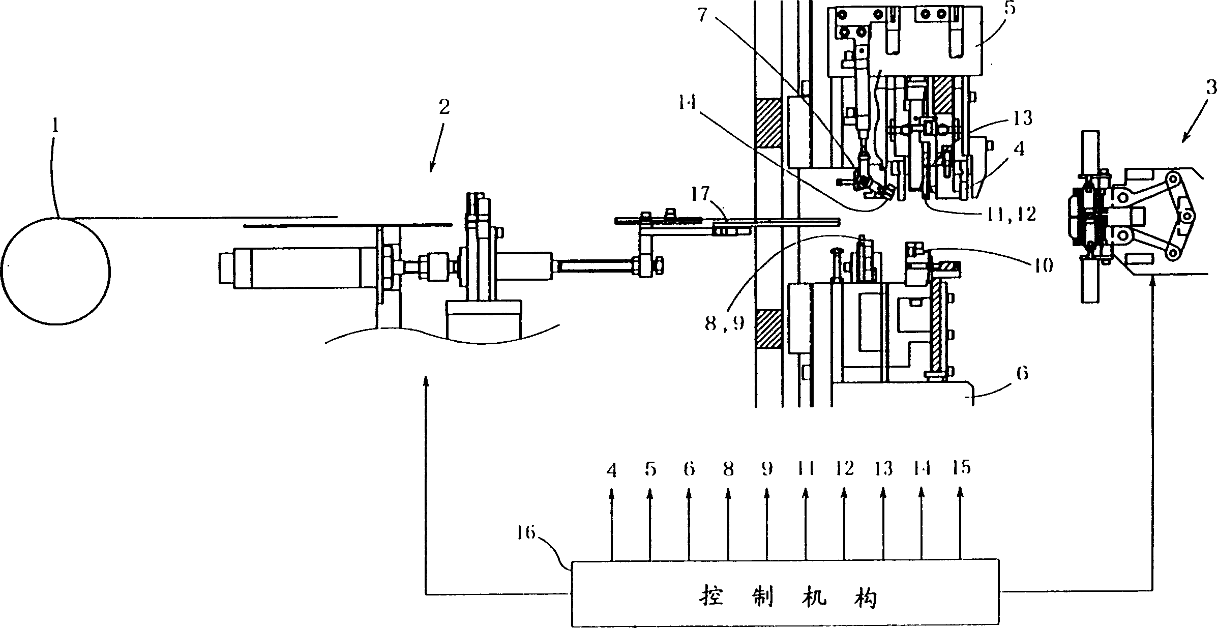
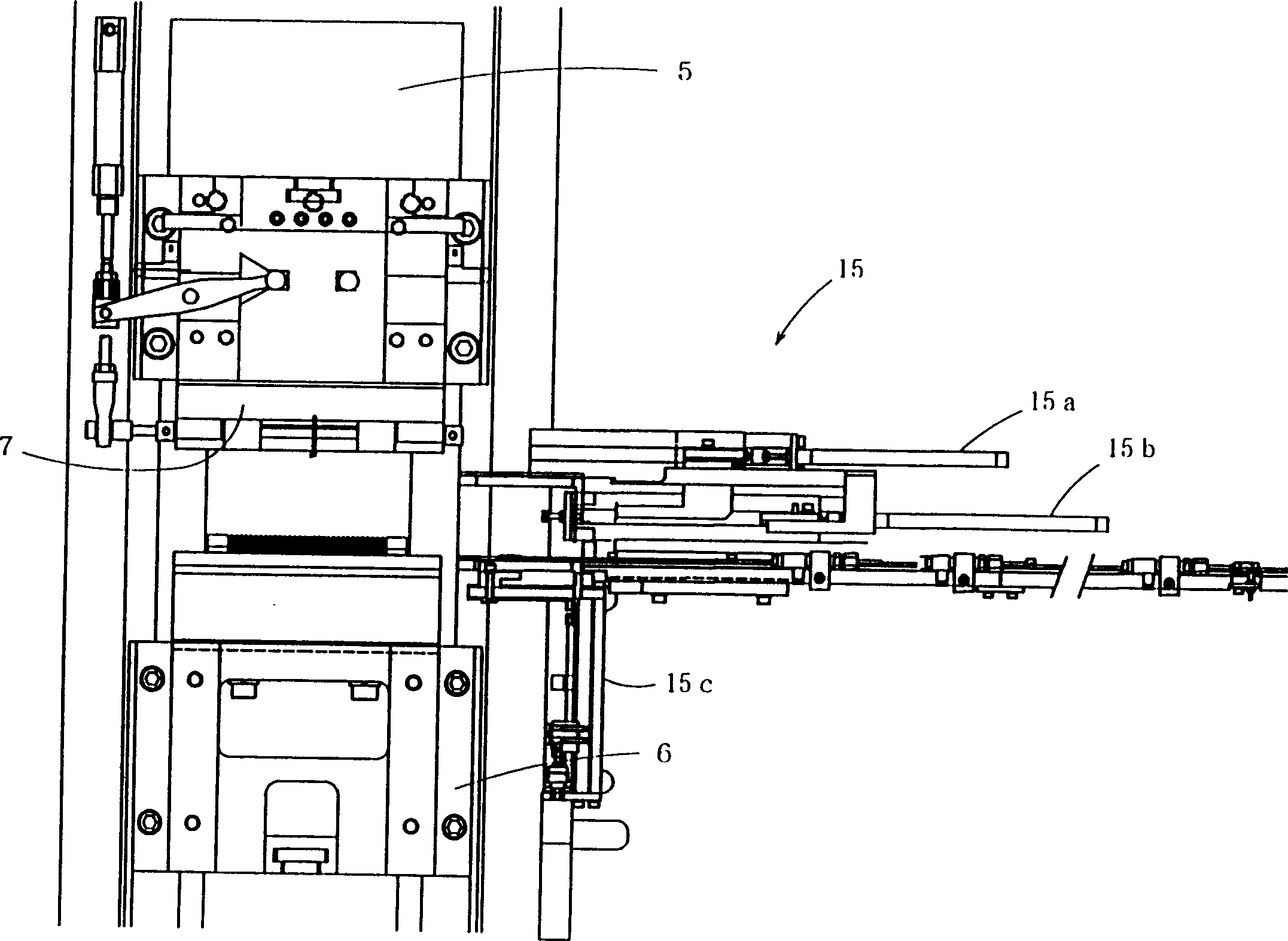
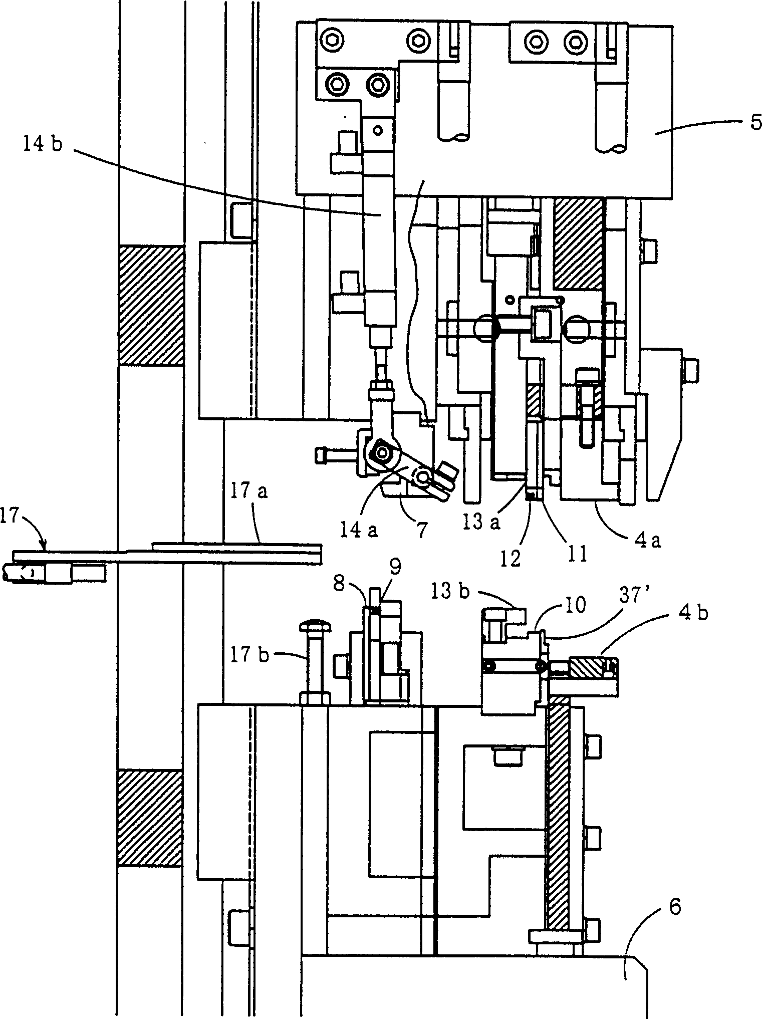
The invention provides a combined pressure welding station and an automatic pressure welding machine equipped with the pressure welding station. The combined pressure welding station includes: a fixed platform formed with a height difference between the first surface supporting the pressure-bearing surface of the connector housing and the second surface of the staggered locking part; a connector housing formed with an opening for supporting the joint connection part The third surface of the joint connection part of the connection surface and the fourth surface of the connection part of the connector shell surface supporting the opening of the wire insertion port; the movable platform that is arranged on the fixed platform and presses the wire lead-out surface of the connector shell and puts the The connector housing is pressed into the brake mechanism in the third surface, and the movable platform can leave the fixed platform in the height direction.

Description

technical field [0001] The invention belongs to the technical field of automatic pressure welding for pressing electric wires into joint grooves of pressure welding connectors and pressure welding wire cores and grooves. The invention relates to the improvement of pressure welding stations for holding pressure welding connectors. Background technique [0002] An automatic bonding machine generally includes a bonding station that holds a bonded connector, a movable assembly that moves toward and away from the bonding station, and a punch mounted on the movable assembly. On the other hand, the pressure-welded connector has a substantially box-shaped connector housing, a joint that is inserted into a hole in the connector housing and has a groove for a pressure-welded wire core at the top, and an electric wire insertion port that communicates with the joint groove is opened in the connector. On the top surface of the shell, its bottom surface becomes a pressure bearing surface ...

Claims


Application Information

Patent Timeline
IPC IPC(8): H01R13/639H01R9/03H01R43/01
CPCH01R43/01Y10T29/49174Y10T29/5137Y10T29/5138Y10T29/514Y10T29/5145Y10T29/5193Y10T29/53209Y10T29/53213Y10T29/53235H01B13/00
Inventor 今泉博之
Owner JST MFG CO LTD
Why Eureka
Try Eureka