Stirling engine
A Stirling engine, linear motion technology, applied in the direction of engine components, machines/engines, hot gas variable displacement engine devices, etc., can solve problems such as inappropriate
- Summary
- Abstract
- Description
- Claims
- Application Information
AI Technical Summary
Problems solved by technology
Method used
Image

Examples
Embodiment Construction
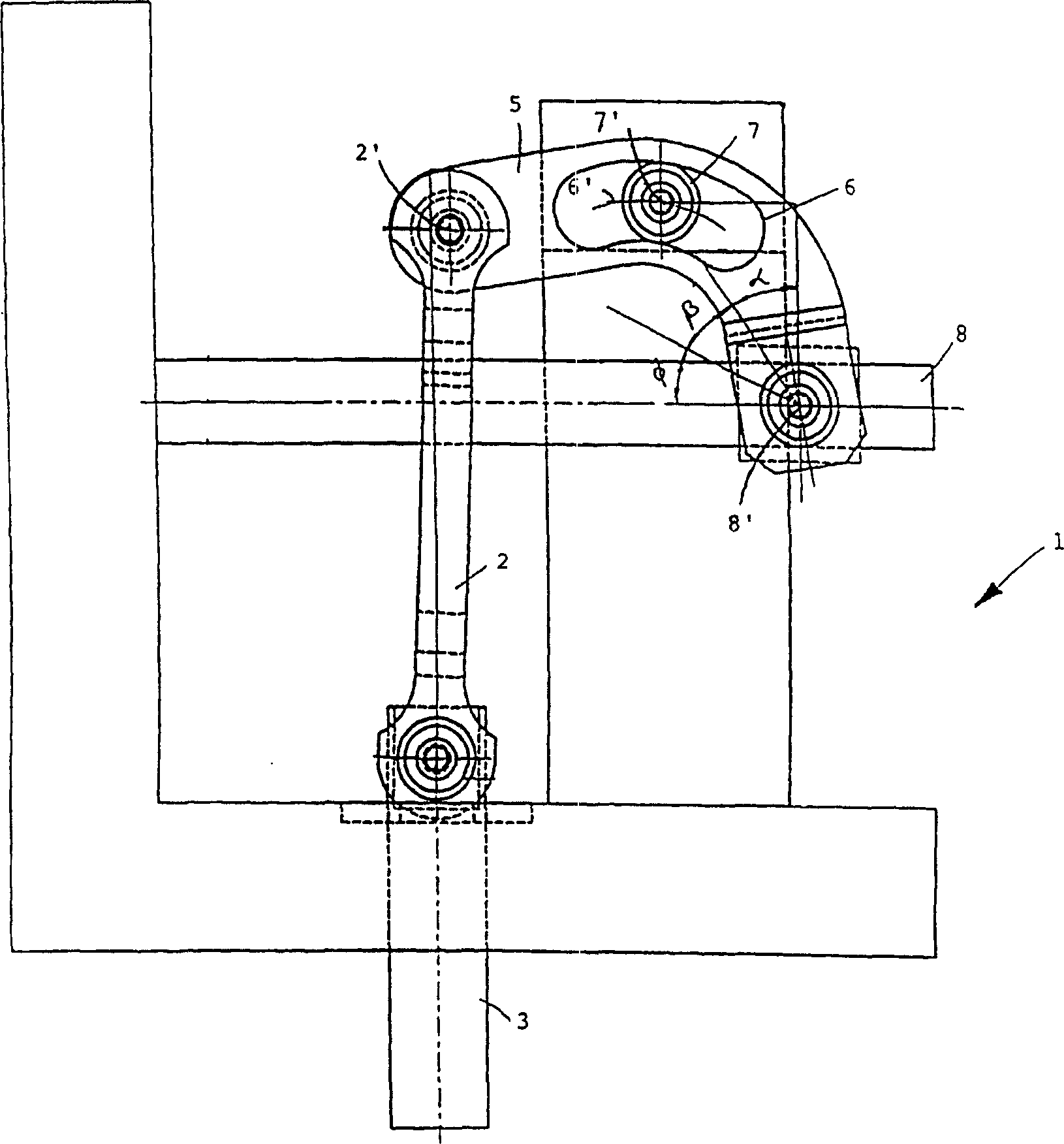
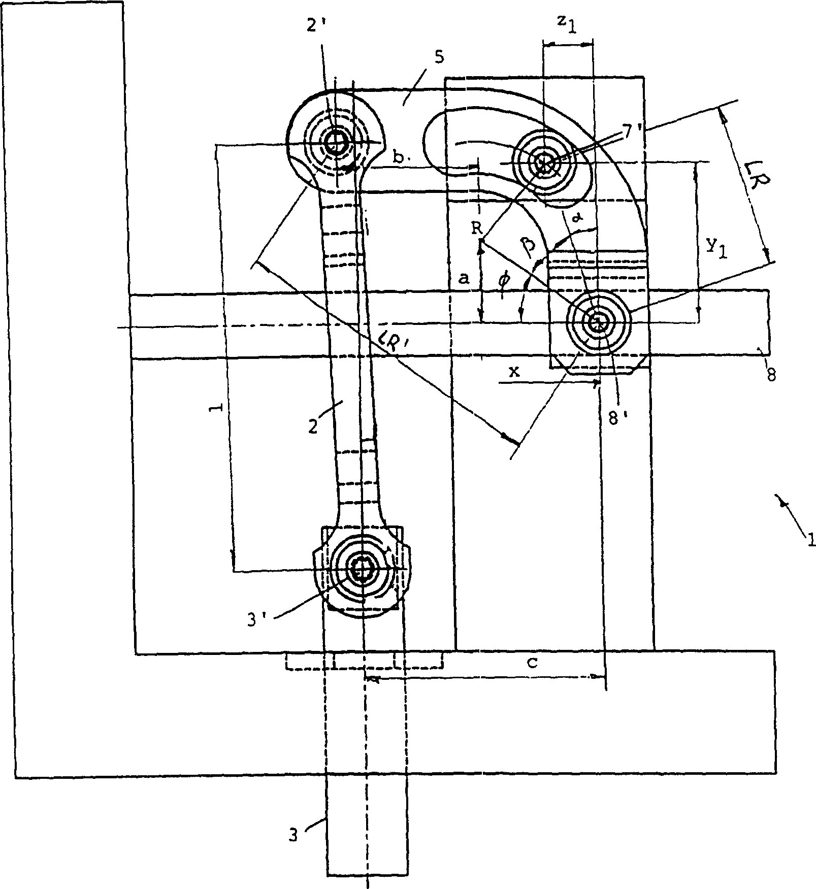
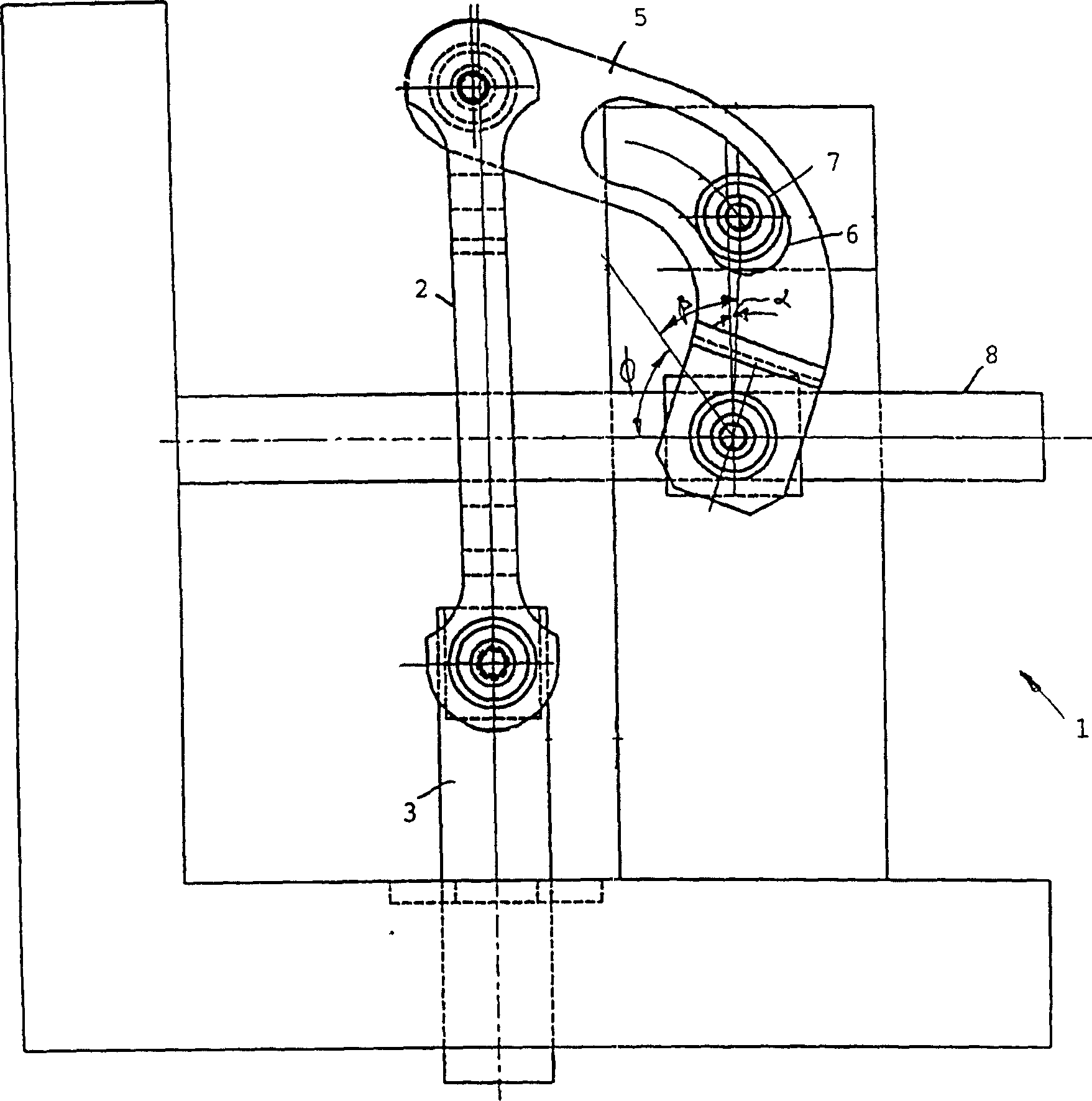
[0056] exist Figures 1 to 3 In , a device 1 for linear motion conversion control is shown, in which there is a connecting rod 2 used as a driving part, which is hingedly connected to a piston rod 3 of an exhaust piston 4 of a Stirling engine ( Figure 6 ). Via shaft 2', connecting rod 2 is also hingedly connected to lever 5, which has a given control curve in the form of connecting rod 6, in which there is provided a shaft which is freely rotatable about shaft 7' and serves as the pivot point of lever 5. Roller 7 (hence, also called "roller bar"). The other end of the lever 5 deviated at an angle of 90° is hingedly connected to the driven rod 8 around the shaft 8 ′, and the linear motion of the exhaust piston rod 3 is transmitted to the rod 8 . Driven rod 8 is linearly installed successively, but turns 90 ° from the linear motion direction of exhaust piston rod 3.
[0057] From Figures 1 to 3 It can be clearly seen in , that the fulcrum of the lever 5 moves along the cur...
PUM
 Abstract
Description
Claims
Application Information
 - R&D Engineer
- R&D Manager
- IP Professional
- Industry Leading Data Capabilities
- Powerful AI technology
- Patent DNA Extraction
Browse by: Latest US Patents, China's latest patents, Technical Efficacy Thesaurus, Application Domain, Technology Topic.
© 2024 PatSnap. All rights reserved.Legal|Privacy policy|Modern Slavery Act Transparency Statement|Sitemap