Method, device and system for amplifying burst optical signals

一种发光信号、信号光的技术,应用在光通信领域,能够解决增益过冲浪涌、光信号失真、传输信号受损等问题,达到实现保真、提升瞬态响应速度的效果

Active Publication Date: 2011-07-27
HUAWEI TECH CO LTD
View PDF4 Cites 7 Cited by
  • Summary
  • Abstract
  • Description
  • Claims
  • Application Information

AI Technical Summary

Problems solved by technology

When from no signal light input to signal light input, because the pump light power at this time is higher than that when there is signal light input, it will cause serious gain oversurf surge, which lasts for tens of microseconds Left and right, causing serious damage to the transmission signal, resulting in distortion of the optical signal

Method used


Image

  • Method, device and system for amplifying burst optical signals
  • Method, device and system for amplifying burst optical signals
  • Method, device and system for amplifying burst optical signals

Examples


Embodiment 1

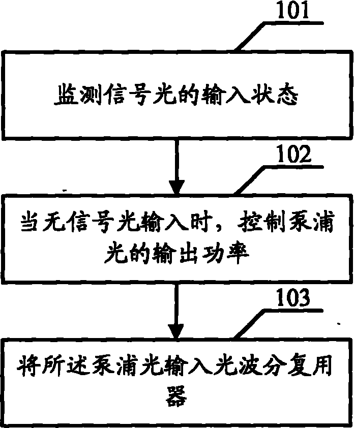
[0025] Embodiment one, such as figure 1 As shown, the embodiment of the present invention provides a method for amplifying a burst optical signal, including:

[0026] 101: Monitor the input state of the signal light;

[0027] The monitoring method can be monitored by a light detector, whether there is signal light input, of course, it is also possible to further monitor the power of the input signal light, which is not limited in the embodiment of the present invention; in addition, it is possible to monitor whether there is signal light input The method is not limited in the embodiments of the present invention.

[0028] 102: When there is no signal light input, control the output power of the pump light so that the gain medium has output optical power, and the output optical power is less than the maximum optical power that the gain medium can output when there is signal light input;

[0029] Before the pump light generated by the above pump source is controlled, it can be...

Embodiment 2

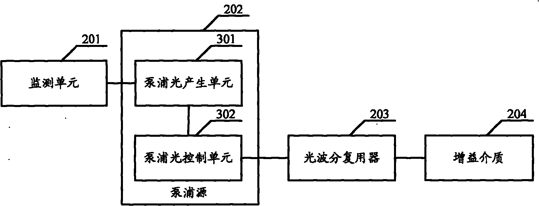
[0036] Embodiment two, such as figure 2 As shown, the embodiment of the present invention also provides a burst optical amplifier, including:

[0037] A monitoring unit 201, configured to monitor the input state of the signal light;

[0038] The pumping source 202 is used to generate pumping light. When no signal light is input, the output power of the pumping light is controlled so that the gain medium has output optical power, and the output optical power is less than the output power of the gain medium when there is signal light input. The maximum optical power of , and input the above pump light into the optical wavelength division multiplexer;

[0039] The optical wavelength division multiplexer 203 is used to input the signal light and the pump light into the gain medium after multiplexing;

[0040] The gain medium 204 is used to amplify the input signal light and output it.

[0041] Optionally, as in image 3 As shown, the above-mentioned pump source 202 includes: ...

Embodiment 3

[0050] Embodiment three, such as Figure 5 As shown, the embodiment of the present invention also provides an optical communication system, including: any burst optical amplifier 501 in Embodiment 2; the burst optical amplifier 501 is connected to the optical burst signal source 502 and the burst optical optical receiver 503;

[0051] The above-mentioned burst optical amplifier 501 is used to receive the burst optical signal generated by the optical burst signal source 502 through an optical fiber; after amplifying the above-mentioned burst optical signal, send it to the burst optical receiver 503 through an optical fiber.

[0052] The above optical communication system can be an optical communication using a burst optical amplifier for a passive optical network (Passive Optical Network, PON) optical burst switching (Optical Burst Switching, OBS) network, an optical packet switching (Optical Packet Switching, OPS) network, etc. system, the above examples should not be underst...


PUM


Abstract

The embodiment of the invention discloses a method, device and system for amplifying burst optical signals. The method comprises the following steps: monitoring the input state of signal light; when no signal light is input, controlling the output power of pump light so that a gain medium has output optical power, and the output optical power is less than the maximum optical power output by the grain medium when signal light input exists; and inputting the pump light to a wavelength division multiplexer (WDM) so that the WDM combines the signal light and the pump light and then inputs the combined signal light and pump light to the grain medium. By using the method, when the no signal light is input, the power of the pump lights is controlled, thus improving the transient response speed of an optical amplifier, avoiding the problems of the surge and slow start of the optical amplifier, and realizing the fidelity of the burst optical signals in the amplification process.

Description

technical field [0001] The present invention relates to the technical field of optical communication, in particular to a burst optical signal amplification method, device and system. Background technique [0002] In the optical communication network, there is a kind of signal light that is composed of different optical signal packets in time, and the time between each optical signal packet is discontinuous, there is a certain time interval without light, and the power amplitude between two adjacent optical signal packets May not be continuous. Such a signal is called a burst optical signal. Currently, such burst optical signals exist in optical switching systems composed of Optical Packet Switching (Optical Packet Switching, OPS) technology or Optical Burst Switching (Optical Burst Switching, OBS) technology and passive optical networks ( Passive Optical Network, PON) system. The equipment, instruments or systems that generate such burst optical signals are collectively r...

Claims


Application Information

Patent Timeline
Patent Type & Authority Applications(China)
IPC IPC(8): H04B10/17H04B10/08H04B10/293
CPCH01S3/1613H04B10/2931H01S3/1616H01S3/1608H01S3/10015H04B10/296H01S3/06754
Inventor 丁锋刘鸿
Owner HUAWEI TECH CO LTD
Why Eureka
Try Eureka