Power control circuit and electronic ballast with the same

An electronic ballast and power control technology, applied in the direction of converting DC power input to DC power output, output power conversion device, control/regulation system, etc., can solve the problem of rising circuit costs, general products without structure, and unable to achieve real-time adjustment Power and other issues

Inactive Publication Date: 2009-02-18
陈建志
View PDF1 Cites 8 Cited by
  • Summary
  • Abstract
  • Description
  • Claims
  • Application Information

AI Technical Summary

Problems solved by technology

[0016] However, in the prior existing power control circuit 3, the current detection unit 34 detects once per cycle, and what the voltage detection unit 33 detects is the average value of the output voltage Vo, and the two detection units After the measurement results are added together, the response of the current detection will be slowed down, and the purpose of adjusting the power in real time cannot be achieved.
In addition, when the load R is open or short-circuited, the signal detected by the current detection unit 34 or the voltage detection unit 33 is zero, so the power switch unit 32 will be turned on, causing the output voltage Vo to be equal to the input voltage Vi, The output transient response is very poor, so that the voltage stress at the rear stage of the power control circuit 3 (such as: full bridge commutation circuit 4) is equal to the previous stage

Method used


Image

  • Power control circuit and electronic ballast with the same
  • Power control circuit and electronic ballast with the same
  • Power control circuit and electronic ballast with the same

Examples


Embodiment Construction

[0068]In order to further explain the technical means and effects of the present invention to achieve the intended purpose of the invention, the power control circuit proposed according to the present invention and the electronic ballast with the power control circuit are described below in conjunction with the accompanying drawings and preferred embodiments. Specific embodiments, structures, features and effects thereof are described in detail below.

[0069] The aforementioned and other technical contents, features and effects of the present invention will be clearly presented in the following detailed description of preferred embodiments with reference to the drawings. Before the present invention is described in detail, it should be noted that in the following description, similar elements are denoted by the same numerals.

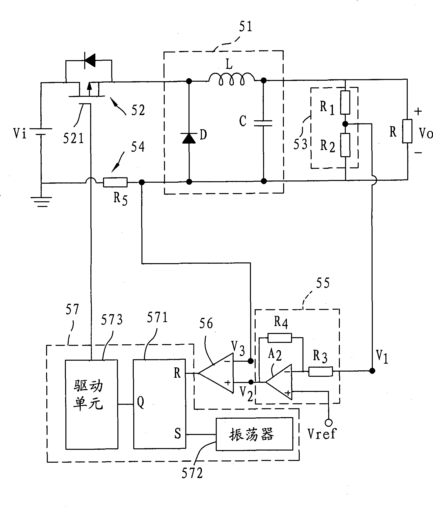
[0070] see image 3 Shown is the circuit diagram of the first preferred embodiment of the power control circuit of the present invention. The power c...


PUM


Abstract

The invention relates to a power control circuit and an electric stabilizer with the same. the power control circuit, which can regulate power effectively, includes a load circuit, a power switch unit, a voltage detecting unit, an error amplifier, a current detecting unit, a comparator and a drive die set, wherein the load circuit being connected with loads and outputting an output voltage; the power switch unit receiving an input voltage to provide for the load circuit in switch; the voltage detecting unit detecting the output voltage and generating a first voltage signal; the error amplifier receiving the first voltage signal and a reference voltage, and outputting a second voltage signal; the current detecting unit detecting the current across the power switch unit and generating a third voltage signal; the comparator comparing the second and the third voltage signals; the drive die set generating a drive signal based on the comparative result of the comparator; the driver power switch unit switching, controlling and providing a load power. The electric stabilizer includes a power control circuit, a rectification circuit and a commutation circuit. The invention can regulate power instantly, and saves cost and is suitable for high illumination intensity air discharge lamp.

Description

technical field [0001] The invention relates to a power control circuit and an electronic ballast with the power control circuit, in particular to a power control circuit suitable for high-illuminance gas discharge lamps and an electronic ballast with the power control circuit. Background technique [0002] The equivalent impedance of high intensity discharge (HID) lamps will increase with time, so in order to maintain the stable lumen output of the lamp tube, the lamp tube needs to receive a stable power, so a power control is required A circuit is used to control the power supplied to the lamp. [0003] US Patent Publication No. 2006 / 0261746 A1, titled "Power control circuit for controlling rated power supplied to a load", proposes a power control circuit, and the power control circuit is suitable for use in an electronic ballast of a high-intensity gas discharge lamp . [0004] Please refer to FIG. 1 , which is a circuit diagram of a conventional electronic ballast. Th...

Claims


Application Information

Patent Timeline
IPC IPC(8): H02M3/156H05B41/28
Inventor 陈建志
Owner 陈建志
Why Eureka
Try Eureka