
Magnetic resonance wireless power transmission device capable of adjusting resonance frequency

A technology of wireless power transmission and resonant frequency, which can be used in transmission systems, circuit devices, near-field transmission systems, etc., and can solve problems such as reducing the overall efficiency of wireless power transmission systems.

Inactive Publication Date: 2017-04-19
MAPS
View PDF7 Cites 7 Cited by
  • Summary
  • Abstract
  • Description
  • Claims
  • Application Information

AI Technical Summary

Problems solved by technology

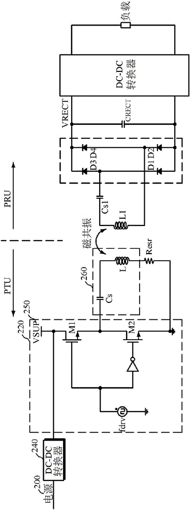
However, additional cost is required to configure the DC-DC converter 240, and there is a risk that losses in the DC-DC converter 240 will reduce the overall efficiency of the wireless power transfer system

Method used


Image

  • Magnetic resonance wireless power transmission device capable of adjusting resonance frequency
  • Magnetic resonance wireless power transmission device capable of adjusting resonance frequency
  • Magnetic resonance wireless power transmission device capable of adjusting resonance frequency

Examples


Embodiment approach

[0124] The simulation results obtained using the above parameters when the tuning voltage Vtune was varied between 1 and 5 are shown in Figure 18 middle. refer to Figure 18 , when the tuning voltage Vtune decreases, the duty cycle becomes smaller. Therefore, the resonance frequency increases, and the output current of the class D power amplifier increases. When the tuning voltage Vtune increases, the output current decreases. In other words, the lower the tuning voltage Vtune, the more energy supplied to the PRU. Such as Figure 19 As shown, it can be seen that when the tuning voltage Vtune becomes lower, the rectifier voltage VRECT on the PRU side increases, and when the tuning voltage Vtune becomes higher, the rectifier voltage VRECT decreases. Meanwhile, the above simulation is just an exemplary embodiment for proving the effect of the present invention, and the present invention is not limited thereto.

[0125] Figure 20 is a circuit diagram of a type II wireless...


PUM


Abstract

A magnetic resonance wireless power transmission device capable of adjusting resonance frequency is disclosed. A wireless power transmission device according to an embodiment of the present invention comprises: a power amplifier for amplifying a wireless power signal using a driving frequency signal; a resonator for configuring a resonance tank and wirelessly transmitting, through magnetic resonance, the wireless power signal output from the power amplifier using a resonance frequency of the resonance tank; and a resonance control unit for controlling a duty ratio using a frequency applied to the resonator or a frequency signal generated by the resonator and adjusting the resonance frequency of the resonator.

Description

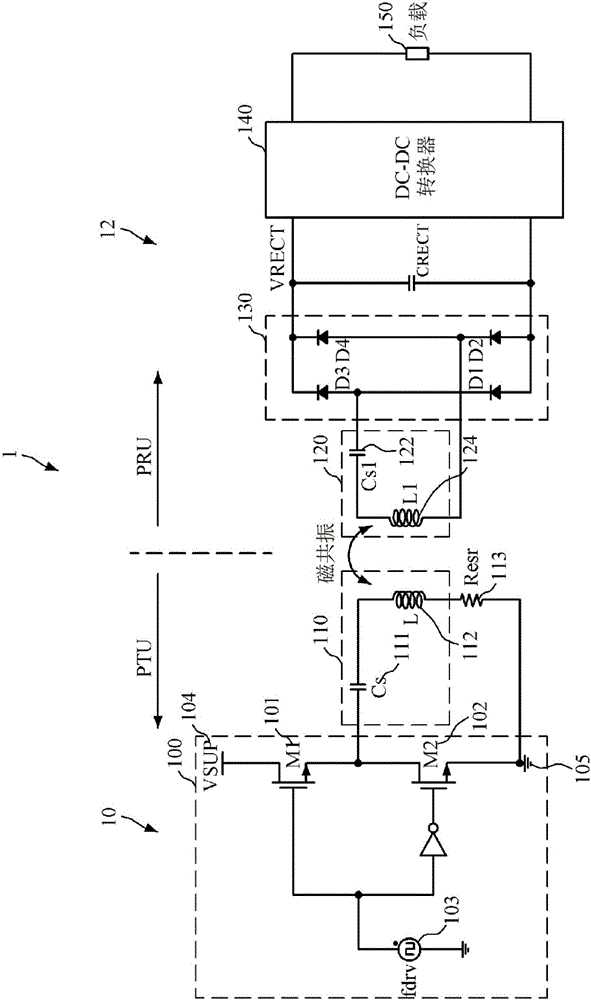
technical field [0001] The present invention relates to magnetic resonance wireless power transmission technology, and more particularly to a wireless power transmission technology using magnetic resonance. Background technique [0002] figure 1 It is a structural diagram of a general magnetic resonance wireless power transmission system. [0003] refer to figure 1 The magnetic resonance wireless power transmission system 1 includes a power supply unit (Power Transmitting Unit, hereinafter referred to as PTU) 10 that wirelessly provides a power signal through magnetic resonance, and a power receiving unit (Power Receiving Unit, hereinafter referred to as PTU) that receives a power signal from the PTU 10. called PRU)12. [0004] The PTU 10 includes a power amplifier 100 and a resonator 110 . The power amplifier 100 includes N-channel metal oxide semiconductor (NMOS) M1 101 and M2 102 , and the resonator 110 includes a transistor Cs 111 and an inductor L 112 . exist figu...

Claims


Application Information

Patent Timeline
Patent Type & Authority Applications(China)
IPC IPC(8): H02J50/12
CPCH03F3/3015H03F3/45475H03F2200/541H03F2203/45512H03F2203/45528H03F2203/45594H03F2203/45604H02J50/12H03F3/2173H03F2200/391Y02E60/00H02J50/80H03H3/0077H03H2003/0414Y04S40/121H04B5/24H04B5/79H03F2200/243
Inventor 黄钟泰申铉翊李东洙李钟勋全商吾宋益圭金旲昊李焌
Owner MAPS
Learn More