Method for locking network equipment

A technology of network equipment and equipment, which is applied in the field of communication, can solve problems such as easy theft, central equipment is easy to disguise, increase network overhead, etc., and achieve the effects of reducing accidental losses, preventing theft, and reducing communication traffic

Inactive Publication Date: 2005-12-14
HUAWEI TECH CO LTD
View PDF0 Cites 2 Cited by
  • Summary
  • Abstract
  • Description
  • Claims
  • Application Information

AI Technical Summary

Problems solved by technology

The second type of network equipment is more likely to be stolen if it is set up outdoors when it is working. For example, when the operator provides Ethernet access, the Ethernet switch is usually placed in the corridor, and the security mechanism provided is only placed on it. In the locked iron box, the thief only needs to pick the lock to steal the Ethernet switch for huge profits
In this way, the network device can be locked in a network to a certain extent, but some network devices (such as Ethernet switches in Ethernet) can still be used in networks with low reliability requirements, even if such network devices cannot communicate with the center If the device communicates normally, the network device can still work for a certain period of time (such as half an hour), then restart, and then work for a certain period of time, and work in this cycle. Therefore, the existing technology does not reliably lock the network device in the network.
In addition, the existing technology also has the following disadvantages: first, the timing communication mechanism makes the network communication too frequent and increases the network overhead; second, the communication between the network equipment and the central equipment does not provide enough encryption mechanism, and the central equipment is easy to disguise. The masquerading central device can make network devices work normally in the network

Method used


Image

  • Method for locking network equipment
  • Method for locking network equipment

Examples


Embodiment Construction

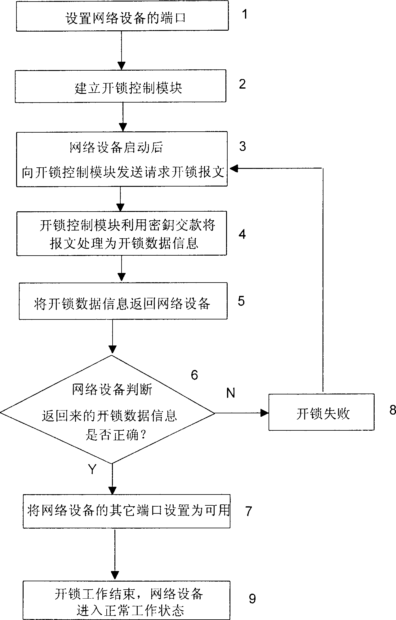
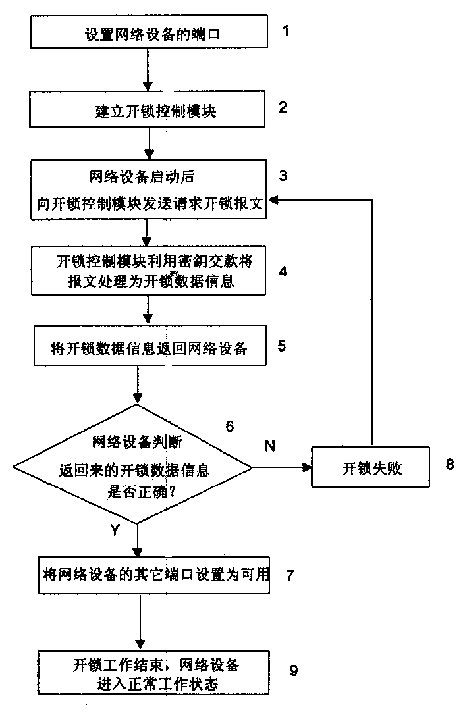
[0016] The specific embodiment of the present invention is described as follows in conjunction with accompanying drawing: the method for locking network equipment comprises:

[0017] Step 1: Set up the ports of the network device: set some ports of the network device to be available after startup, and some ports to be available after startup and unlocking. The port used by the control module for communication is set to be available after startup;

[0018] Step 2: Establish an unlocking control module in the network for processing the unlocking request sent by the network device and controlling the unlocking of the network device; the unlocking control module manages the network device identification of each network device in the network and the key corresponding to the network device At the same time, it can process the unlocking request sent by the network device to realize effective control of whether the network device is unlocked. The unlocking of the network device means ...


PUM


Abstract

The invention relates to a method for locking network equipment in a network. First set up the ports of the network device, so that some ports are set to be available after startup, and some ports are set to be available after startup and through the unlocking process; Control module; after the network device starts, it sends an unlocking request to the unlocking control module; the unlocking control module sends the unlocking request back to the network device after corresponding processing, and completes the unlocking work. In this way, if the network device is not used in a predetermined network, or the user of the network device does not know information such as its key, the network device cannot be put into a working state. Therefore, the present invention can reliably lock network equipment in a certain network, and only users with legal identities can use the network equipment, thereby effectively preventing network equipment from being stolen and reducing accidental losses of network operators.

Description

technical field [0001] The invention relates to the field of communication technology, in particular to a method for locking network equipment into a network. Background technique [0002] At present, network equipment can be divided into two types according to the relationship between network equipment and the network where it is located. One type of network equipment cannot work normally without its own network, such as the base station in the GSM system. Outdoors, you don’t have to worry about being stolen. Another kind of network equipment is different. This kind of network equipment can adapt to more working environments, such as Ethernet switches. Usually Ethernet switches can operate without complicated environments, and do not require Any configuration will work fine. The second type of network equipment is more likely to be stolen if it is set up outdoors when it is working. For example, when the operator provides Ethernet access, the Ethernet switch is usually pla...

Claims


Application Information

Patent Timeline
Patent Type & Authority Patents(China)
IPC IPC(8): H04L9/00
Inventor 王建
Owner HUAWEI TECH CO LTD
Why Eureka
Try Eureka