Supercharge Your Innovation With Domain-Expert AI Agents!

Rotating mechanism of close compressor

A hermetic compressor and rotary mechanism technology, applied in the field of compressors, can solve the problem that the crankshaft 5 cannot be rotated, and achieve the effects of smooth rotation, reduced driving load, and smooth lubrication

Inactive Publication Date: 2005-12-28
LG ELECTRONICS (TIANJIN) APPLIANCES CO LTD
View PDF0 Cites 0 Cited by
  • Summary
  • Abstract
  • Description
  • Claims
  • Application Information

AI Technical Summary

Problems solved by technology

Coupled with the friction between the support surface 5t and the truss surface 2t, the crankshaft 5 cannot rotate

Method used


Image

  • Rotating mechanism of close compressor
  • Rotating mechanism of close compressor
  • Rotating mechanism of close compressor

Examples


Embodiment Construction

[0016] Embodiments of the present invention are further described below in conjunction with accompanying drawings:

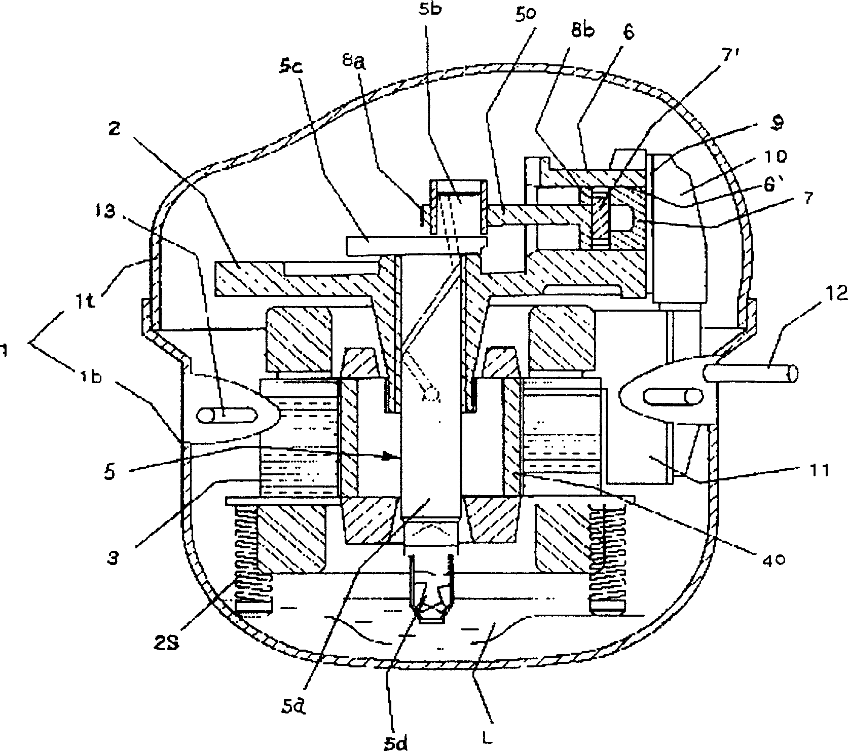
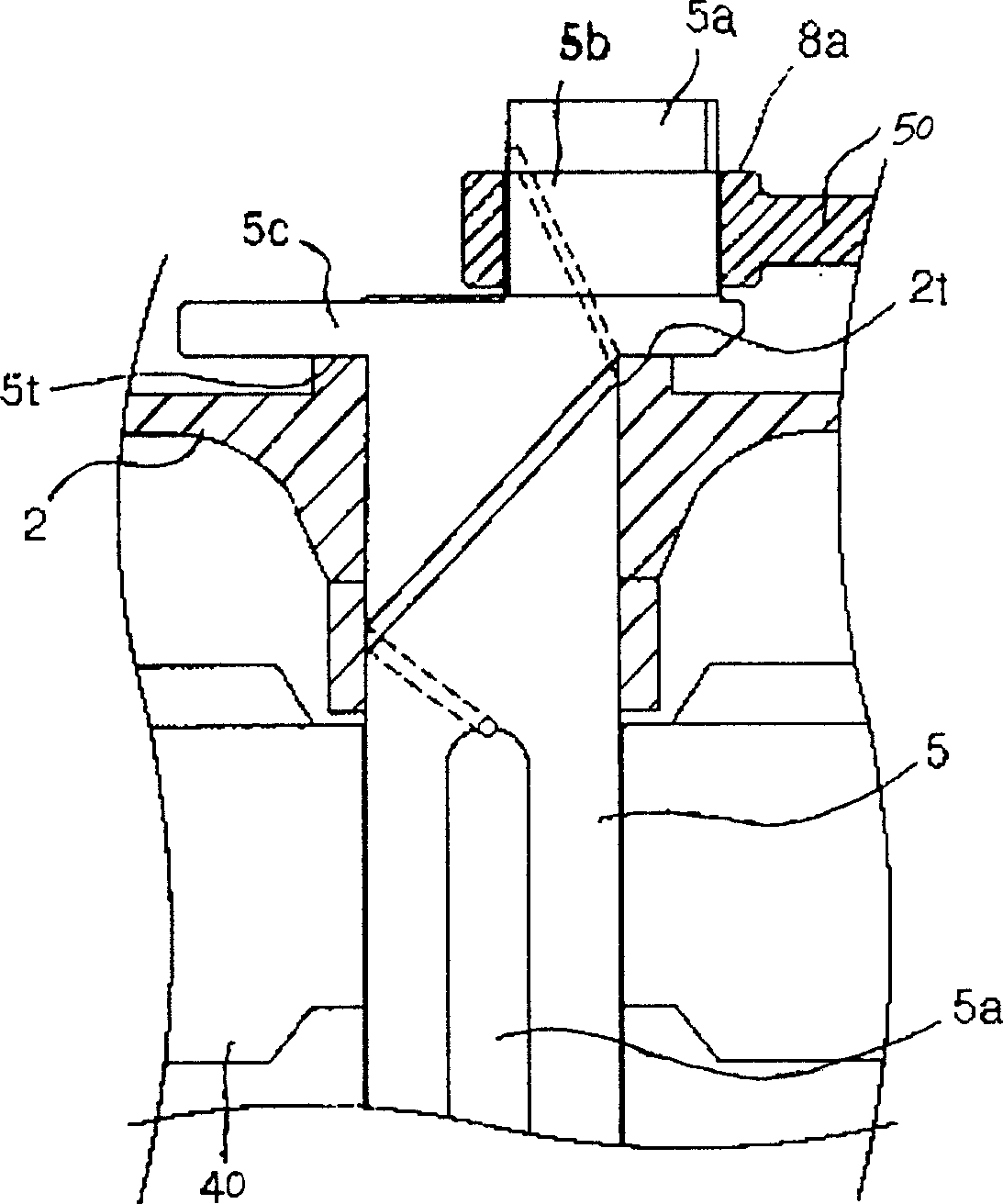
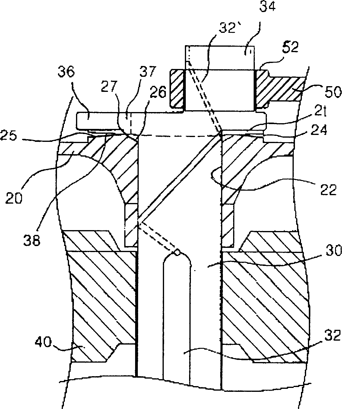
[0017] The present invention is a rotary mechanism of a hermetic compressor. Its structure includes a crankshaft 30 connected to the motor rotor and installed in the central through hole 22 of the frame 20. There is a through oil channel in the crankshaft 30 from the lower end to the upper end of the eccentric shaft 34. The contact between the truss surface 24 above the frame 20 and the balance weight 36 of the crankshaft 30 and the support surface 38 below the eccentric shaft 34 is a line contact.

[0018] The line contact is the contact line 27 formed by the intersection of the inverted conical surface 26 centered on the center line of the central through hole 22 of the frame 20 and the right conical surface 25 centered on the center line of the central through hole 22 of the frame 20 on the truss surface 24 .

[0019] The contact line 27 on the truss surface ...


PUM


Abstract

The invention is a rotary mechanism of a hermetic compressor. The present invention relates to a rotary mechanism of a compressor. The structure of the present invention includes that the crankshaft connected with the motor rotor is installed in the central through hole of the frame, and there is a through oil channel in the crankshaft from the lower end to the upper end in the eccentric shaft, and the truss surface on the frame is connected with the balance weight of the crankshaft and the eccentric shaft. The contact of the support surface is a line contact. The beneficial effects of the present invention are: the contact surface between the crankshaft of the rotating mechanism of the present invention and the frame supporting the crankshaft is a line contact, the contact area is the smallest, and the mutual friction force can be effectively reduced, so that the rotation of the crankshaft is smoother. Less force is required to start the crankshaft, and the initial driving force required to start the compressor is significantly reduced. The invention can conveniently supply oil required for lubrication between the support surface of the crankshaft and the truss surface of the machine frame, so that the lubrication is smooth, the driving load is reduced, the abrasion is minimized, and the service life of the compressor can be prolonged.

Description

technical field [0001] The present invention relates to a compressor, in particular to a rotary mechanism of a hermetic compressor. Background technique [0002] figure 1 It is a schematic diagram of the internal structure of a hermetic compressor in the prior art. As can be seen from the figure, the upper container 1t and the lower container 1b constitute the inner space of the closed container 1 . Inside the closed container 1 there is a frame 2 . The frame 2 is supported by the spring 2S. A crankshaft 5 is installed through the center of the frame 2, and the crankshaft 5 is contained in the rotor 40, and the rotor 40 and the stator 3 rotate together with the crankshaft 5 under electromagnetic action. [0003] The eccentric shaft 5 b at the upper end of the crankshaft 5 is shifted relative to the rotation center of the crankshaft 5 . There is a balance weight 5c in the opposite direction of the eccentric shaft 5b. The lower end of the crankshaft 5 is equipped with an...

Claims


Application Information

Patent Timeline
Patent Type & Authority Patents(China)
IPC IPC(8): F04B27/08F04B39/02
Inventor 李信熙
Owner LG ELECTRONICS (TIANJIN) APPLIANCES CO LTD
Features
  • R&D
  • Intellectual Property
  • Life Sciences
  • Materials
  • Tech Scout
  • Unparalleled Data Quality
  • Higher Quality Content
  • 60% Fewer Hallucinations
Learn More