


Quick Research
Generate reliable direction feasibility study reports for your R&D in just a few steps.

Technical Q&A
Discover and master advanced knowledge NOW. Basics, ideas, possibilities, all at once.

Find Solutions
As an expert in R&D theories, this can generate solutions to your technical problems instantly.

Evaluate Feasibility
Analyze your overall solution with one click, know your potential R&D risks in advance.

Monitor Landscape
Get weekly tech updates, stay abreast of the latest tech innovations and key insights.
Gas turbine generator and air humidifier
A technology of power generation equipment and gas turbines, applied in the direction of gas turbine devices, mechanical equipment, machines/engines, etc., can solve problems such as lack of research
- Summary
- Abstract
- Description
- Claims
- Application Information
AI Technical Summary
Problems solved by technology
Method used
Image

Examples
Embodiment Construction
[0046] Various embodiments of the present invention will be described below with reference to the accompanying drawings.
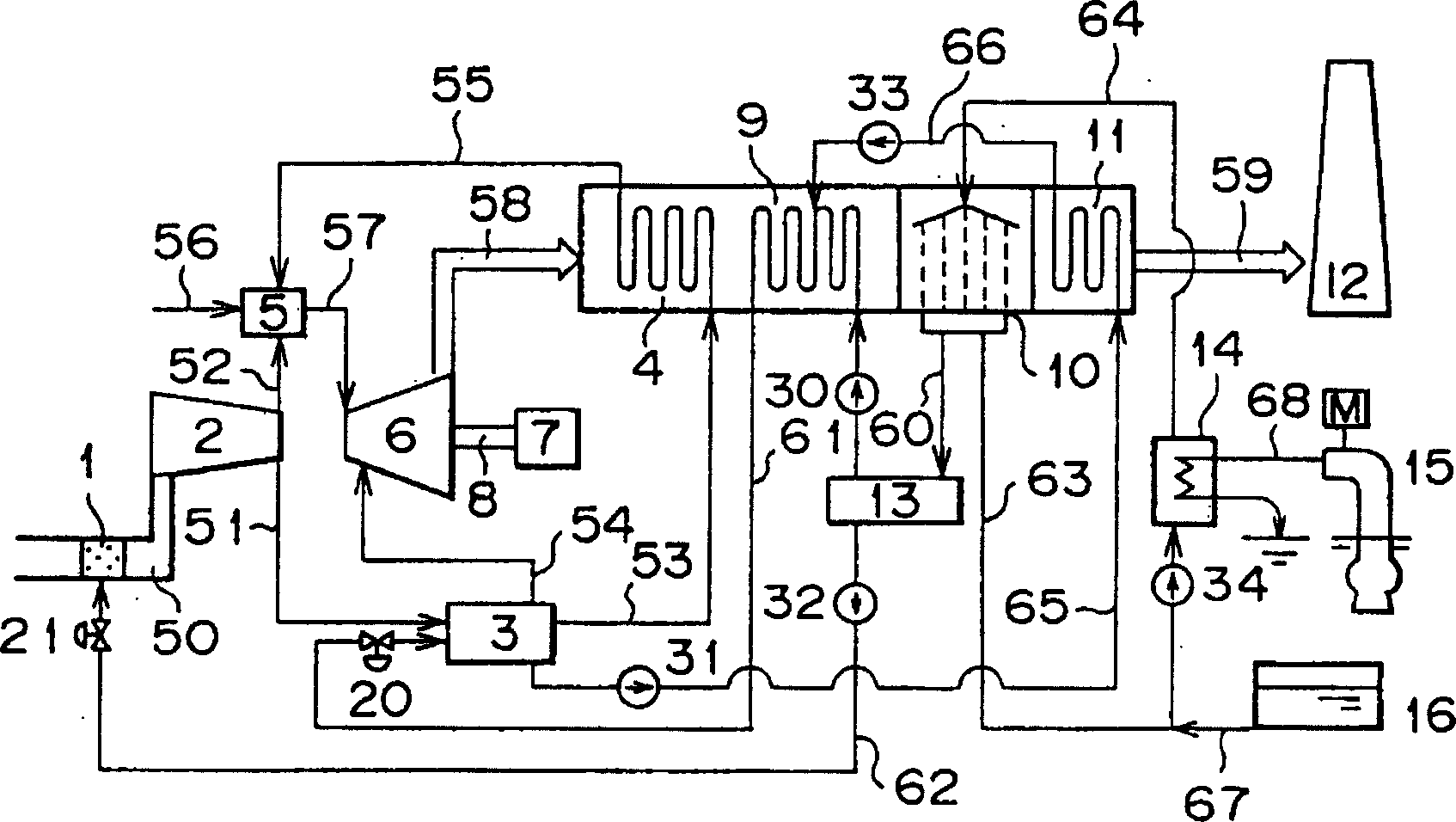
[0047] figure 1 is a system diagram of a gas turbine power plant according to a first embodiment of the present invention. exist figure 1 Among them, the symbol 1 represents the WAC device, which is used to inject water into the air (a); the symbol 2 represents the compressor, which is used to compress the air (a); the symbol 3 represents the air humidifier, which is used to humidify the compressed air (b); 4 represents a regenerator for heating humidified air (c); numeral 5 represents a burner for mixing fuel (d) with humidified air (c) or compressed air (b) and for burning them to produce Combustion gas (e); The mark 6 represents the turbine, driven by the combustion gas (e); The mark 7 represents the generator, which is used to convert energy to generate electricity; The mark 8 represents the turbine rotor, which is used to connect the compressor 2, t...
PUM
 Abstract
Description
Claims
Application Information
 - R&D Engineer
- R&D Manager
- IP Professional
- Industry Leading Data Capabilities
- Powerful AI technology
- Patent DNA Extraction
Browse by: Latest US Patents, China's latest patents, Technical Efficacy Thesaurus, Application Domain, Technology Topic, Popular Technical Reports.
© 2024 PatSnap. All rights reserved.Legal|Privacy policy|Modern Slavery Act Transparency Statement|Sitemap|About US| Contact US: help@patsnap.com