Supercharge Your Innovation With Domain-Expert AI Agents!

Principal axis servo controlling method for optical disk drive

An optical disc drive, servo control technology, applied in the recording of information on the magnetic disk, the configuration/installation of instruments, and heads, etc., can solve problems such as obstacles, and achieve the effect of simplification and saving

Inactive Publication Date: 2006-01-25
LEJIN GUANGDIAN ELECTRONIC CO LTD SHANGHAI
View PDF0 Cites 0 Cited by
  • Summary
  • Abstract
  • Description
  • Claims
  • Application Information

AI Technical Summary

Problems solved by technology

[0015] However, for the above-mentioned spindle servo control operation, an FG signal generator that outputs FG signals corresponding to the number of rotation speeds of the above-mentioned spindle motor is necessary, which becomes an obstacle to the simplification and manufacturing cost saving of the optical disk drive.

Method used


Image

  • Principal axis servo controlling method for optical disk drive
  • Principal axis servo controlling method for optical disk drive
  • Principal axis servo controlling method for optical disk drive

Examples


Embodiment Construction

[0029] Embodiments of the spindle servo control method of an optical disk drive according to the present invention will be described in detail below with reference to the accompanying drawings.

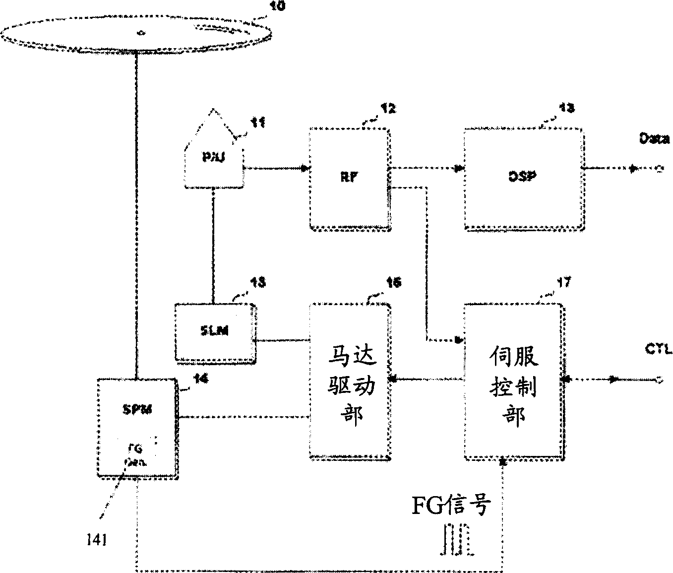
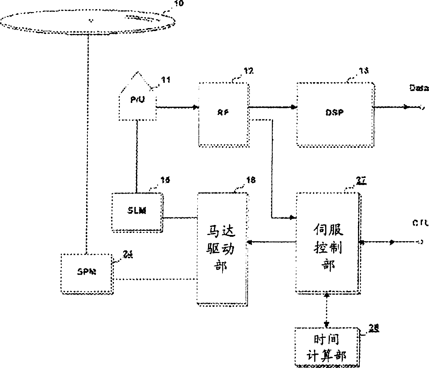
[0030] image 3 is a structural diagram illustrating an optical disc drive manufactured by applying the spindle control method according to the present invention. The above optical disc drive is as referenced figure 1 Description has the following parts.

[0031] The optical pick-up 11 that reads the data that is stored on the optical disc 10 such as CD or DVD; The RF signal that the above-mentioned optical pick-up outputs is processed into the RF signal processing section 12 of the signal of gain and binary (Binary ) and the above-mentioned RF signal The binary signal processed by the processing part 12 is processed into a digital image or a digital signal processing part DSP13 of audio data;

[0032] Spindle motor section SPM24 that rotates the above-mentioned optical disc 10 at h...


PUM


Abstract

The invention is a spindle servo control method of CD driver. In the emergency of stopping high-speed rotating spindle motor of CD driver, it inputs a drive voltage for a certain time to spindle motor of CD driver in positive direction, to make servo motor rotate at a maximum physical speed, then input a plugging voltage corresponding to servo motor's physical speed to the spindle motor, to stop the motor, in result that it does not use FG signal generator in existing technique to safely stop high-speed rotating motor. It can simplify CD driver and save making cost.

Description

(1) Technical field [0001] The invention relates to a spindle servo control method of an optical disk drive, in particular to a spindle servo control method for an optical disk drive that rotates or stops a CD or DVD inserted into the optical disk drive at high speed in a forward / reverse direction. (2) Background technology [0002] figure 1 It illustrates the composition of a common CD-ROM drive, and the above-mentioned CD-ROM drive is composed of the following components. [0003] For example, an optical pickup P / U11 that reads data stored on optical discs 10 such as CDs or DVDs; an RF signal processing unit 12 that processes the RF signal output by the above-mentioned optical pickup into amplification and binary (Binary) signals; The digital signal processing unit DSP13 that processes the binary signal processed by the above-mentioned RF signal processing unit 12 into digital video or audio data; the spindle motor unit SPM14 that rotates the above-mentioned optical disc ...

Claims


Application Information

Patent Timeline
Patent Type & Authority Patents(China)
IPC IPC(8): G11B7/09G11B19/20
Inventor 柳承澔
Owner LEJIN GUANGDIAN ELECTRONIC CO LTD SHANGHAI
Features
  • R&D
  • Intellectual Property
  • Life Sciences
  • Materials
  • Tech Scout
  • Unparalleled Data Quality
  • Higher Quality Content
  • 60% Fewer Hallucinations
Learn More