High sensitivity pressure sensor with long term stability

A pressure sensor, high-sensitivity technology, applied in the pressure difference measurement between multiple valves, fluid pressure measurement using capacitance changes, fluid pressure measurement, etc., to achieve the effect of providing long-term stability

Inactive Publication Date: 2006-04-12
PANAMETRICS
View PDF0 Cites 3 Cited by
  • Summary
  • Abstract
  • Description
  • Claims
  • Application Information

AI Technical Summary

Problems solved by technology

Additionally, in prior art designs, indirect changes in the sensor output required frequent recalibration, or required operation under fine temperature control, signal compensation or other corrections

Method used


Image

  • High sensitivity pressure sensor with long term stability
  • High sensitivity pressure sensor with long term stability
  • High sensitivity pressure sensor with long term stability

Examples


Embodiment Construction

[0030] In addition to the preferred embodiment or embodiments disclosed below, the invention is capable of other embodiments and of being practiced or carried out in various ways. It should therefore be understood that the application of the present invention is not limited to the detailed construction and arrangement of parts set forth in the following description or drawings.

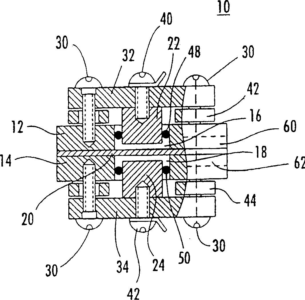
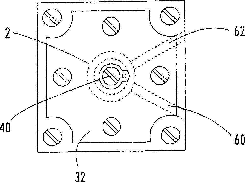
[0031] of the present invention Figure 1-2 The pressure sensor 10 preferably includes a housing having two base plates 12 and 14 defining a first chamber 16 and a second chamber 18 of equal volume. Diaphragm 20 separates and spans chambers 16 and 18 and is clamped between substrates 12 and 14 . A first electrode 22 is located in the first chamber 16, closely spaced from one side of the diaphragm 20 to form a first capacitor therewith. A second electrode 24 is located in the second chamber 18, closely spaced from the opposite face of the diaphragm 20 to form a second capacitor therewith.

[0032] P...


PUM

PropertyMeasurementUnit
thicknessaaaaaaaaaa

Abstract

A high sensitivity pressure sensor with long term stability including a housing with first and second chambers, a membrane (20) separating the first and second chambers, a first electrode located in the first chamber (16) and spaced from one side of the membrane forming a first capacitor therewith, and a second electrode located in the second chamber (18) and spaced from an opposite side of the membrane forming a second capacitor therewith.

Description

technical field [0001] The present invention relates to pressure sensors with long-term stability and high sensitivity for use in various instrumentation fields including gas analysis and Luft type infrared gas analyzers and in photoacoustic and magnetoacoustic analyzer systems. [0002] This application claims priority to US Provisional Application Serial No. 60 / 293,581, filed May 25, 2001, entitled "Instrumental Pressure Sensors." Background technique [0003] The task of measuring low-level gas pressures with long-term stability and high sensitivity is of great importance in various instrumentation fields, especially those involving gas analysis. Various classes of instruments depend on inducing small pressure changes in a gas sample by exposing the gas to a controlled stimulus or environment, such as excitation by light, a magnetic field, or an electric field. For example, Luft-type infrared analyzers as well as photoacoustic and magnetoacoustic analyzers rely on having...

Claims


Application Information

Patent Timeline
Patent Type & Authority Patents(China)
IPC IPC(8): G01L9/12G01L13/06G01L9/00G01L13/02G01L19/02G01L19/04
CPCG01L13/025G01L9/0072G01L9/12G01L9/125G01L19/02
Inventor Y·戈克费尔德
Owner PANAMETRICS
Why Eureka
Try Eureka