Check patentability & draft patents in minutes with Patsnap Eureka AI!

Mouse structure

A mouse and body technology, applied in the field of mouse structure, can solve the problems affecting the appearance of the mouse, uneven brightness, etc.

Inactive Publication Date: 2006-04-19
DARFON ELECTRONICS CORP
View PDF0 Cites 0 Cited by
  • Summary
  • Abstract
  • Description
  • Claims
  • Application Information

AI Technical Summary

Problems solved by technology

However, since the LED is a point light source, it is prone to the disadvantage of uneven brightness, which affects the overall appearance of the mouse.

Method used


Image

  • Mouse structure
  • Mouse structure
  • Mouse structure

Examples


no. 1 example

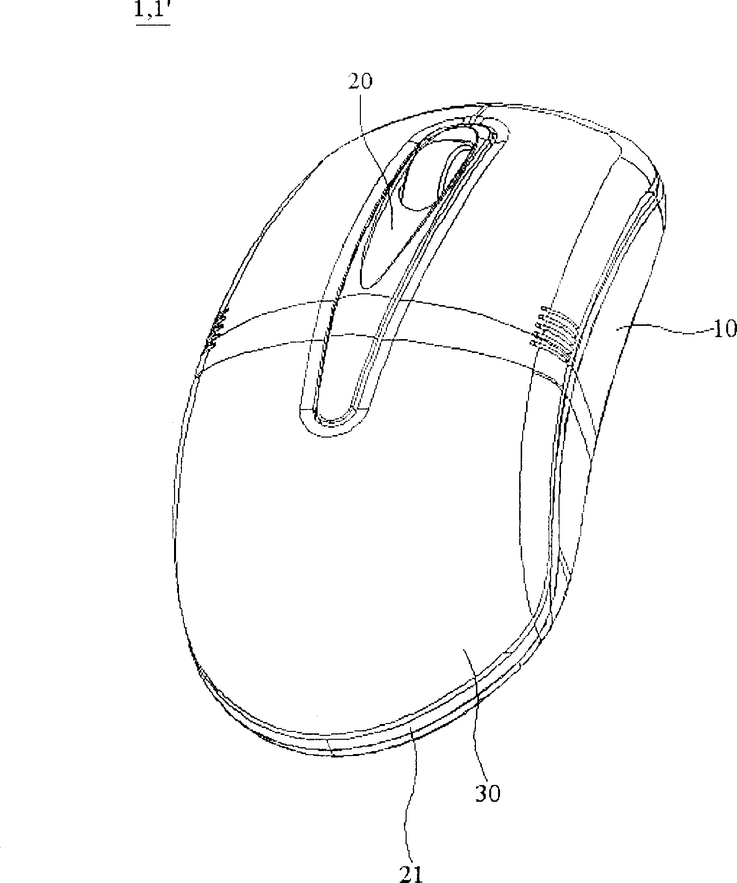
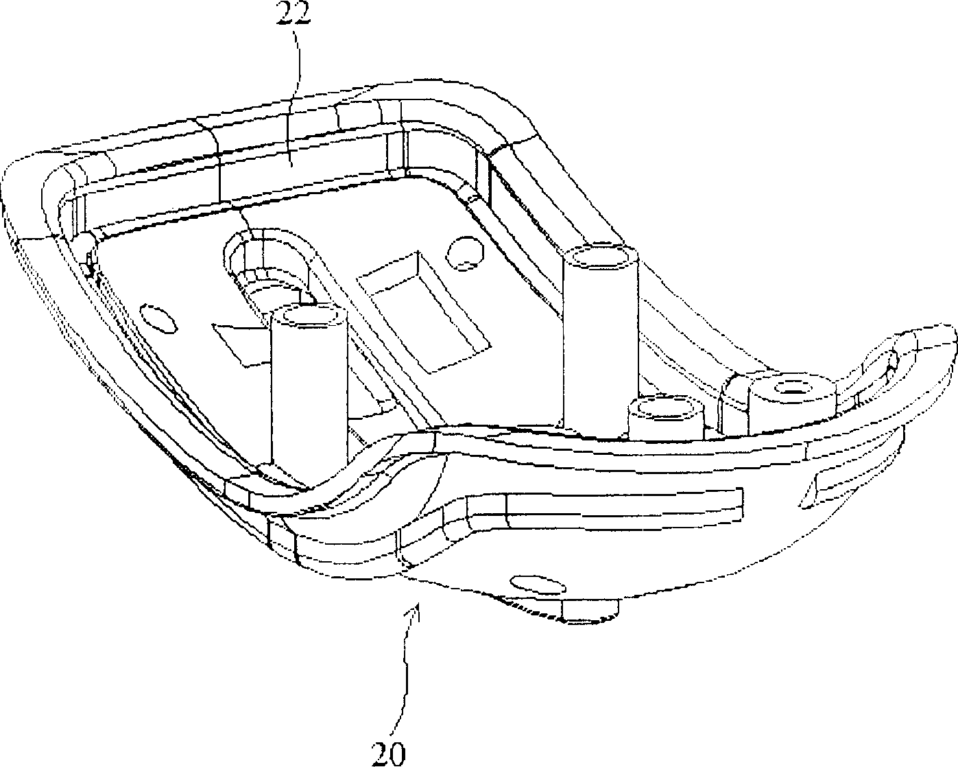
[0027] see figure 1 and figure 2 , the mouse structure 1 of this embodiment mainly includes a body 10 , an upper cover 20 , and a button device 30 . The upper cover 20 is disposed on the main body 10 . The button device 30 is disposed on the upper cover 20 , and at the same time, the upper cover 20 forms an annular transparent portion 21 between the main body 10 and the button device 30 . When the body 10 , the upper cover 20 and the key device 30 are assembled together, the annular transparent portion 21 surrounds the body 10 and the key device 30 .

[0028] Such as figure 2 As shown, the upper cover 20 can be made of a material with high light transmittance, such as plexiglass or transparent plastic. As for the key device 30, it is made of opaque or reflective material.

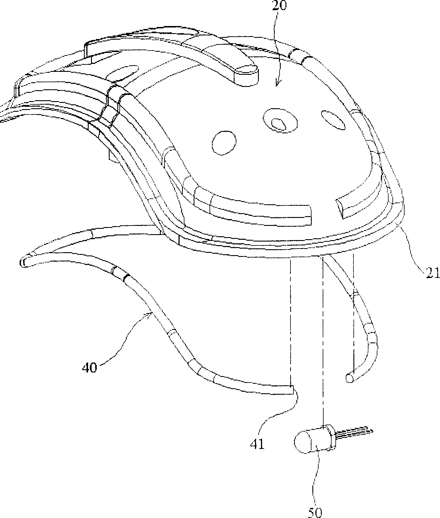
[0029] Such as figure 2 and image 3 As shown, the mouse structure 1 of this embodiment further includes an optical fiber 40 and a first light-emitting component 50 . In addition, the bottom of t...

no. 2 example

[0035] The biggest difference between this embodiment and the first embodiment lies in the difference of the light-emitting device, while the structure and arrangement of the components of the rest of the mouse structure 1' are the same as those of the first embodiment, therefore, the same components are marked with the same symbols, No further description.

[0036] see figure 1 and Figure 4 , the upper cover 20 can be made of a material with high light transmittance, such as plexiglass or transparent plastic. As for the key device 30, it is made of highly reflective material.

[0037] Such as Figure 4 As shown, the mouse structure 1' of this embodiment can have more than one second light emitting assembly 60, and the second light emitting assembly 60 can be directly arranged on the main body 10.

[0038] In addition, when the mouse structure 1' is used as an optical mouse structure, the mouse structure 1' will also have an optical module 70. At this time, the light emit...


PUM


Abstract

The present invention provides one kind of mouse structure including one main body, one top cover, one key unit and one light emitting unit. The top cover is on the main body, the key unit is set on the top cover, and one transparent part is formed in the top cover and between the main body and the key unit. The emitted light from the light emitting unit set between the top cover and the main body penetrates the transparent part outwards.

Description

technical field [0001] The invention relates to a mouse structure, in particular to a mouse structure capable of producing a uniform glare effect. Background technique [0002] Generally speaking, the shape of the mouse is becoming more and more stunning, so the glare effect is often applied to the appearance design of the mouse. For example, LEDs are arranged in the wheel structure of the mouse to make the wheel of the mouse produce a glare effect. However, since the LED is a point light source, it is easy to have the disadvantage of uneven brightness, thus affecting the overall aesthetic appearance of the mouse. Contents of the invention [0003] The purpose of the present invention is to provide a mouse structure, which utilizes the light guiding principle of objects to guide and diverge the light source in the mouse structure to the appearance surface of its upper cover, so as to achieve the glare effect of uniform light emission. [0004] The present invention basica...

Claims


Application Information

Patent Timeline
Patent Type & Authority Patents(China)
IPC IPC(8): G06F3/033G06F3/0354
Inventor 黄俊中
Owner DARFON ELECTRONICS CORP
Features
  • R&D
  • Intellectual Property
  • Life Sciences
  • Materials
  • Tech Scout
  • Unparalleled Data Quality
  • Higher Quality Content
  • 60% Fewer Hallucinations
Learn More