Supercharge Your Innovation With Domain-Expert AI Agents!

Communications systems

A signal and radio frequency signal technology, applied in the field of communication systems, can solve problems such as poor time calibration, and achieve the effect of increasing flexibility

Inactive Publication Date: 2006-04-19
TELEFON AB LM ERICSSON (PUBL)
View PDF0 Cites 0 Cited by
  • Summary
  • Abstract
  • Description
  • Claims
  • Application Information

AI Technical Summary

Problems solved by technology

The problem that often arises, then, is poor time alignment between the "information parameter" (or "information component", i.e. gain and phase (represented in polar form), or between I and Q (represented in Cartesian form)

Method used


Image

  • Communications systems
  • Communications systems
  • Communications systems

Examples


Embodiment Construction

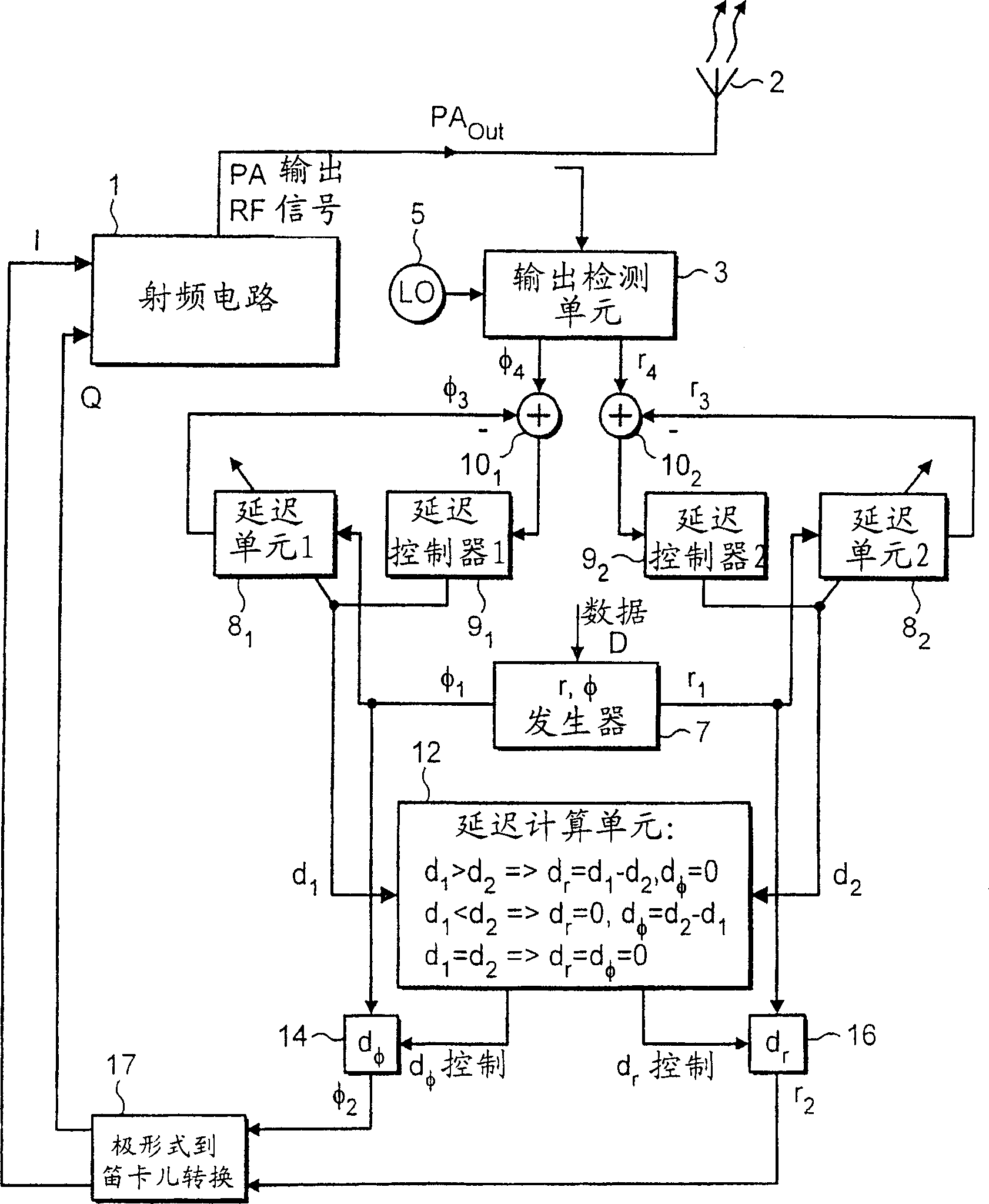
[0080] figure 1 A block diagram is given illustrating a first embodiment of the invention which compensates for a time delay between phase φ and amplitude (envelope) r.

[0081] figure 1 The system shown comprises a radio frequency transmitter with a radio frequency circuit (RF circuit) 1 including a power amplifier which produces a power amplifier output PA which is supplied to an antenna 2 out . RF circuit 1 receives phase and amplitude signals (φ 2 , r 2 ), the output signal is generated from these signals. The working mechanism of RF circuits is well known and will not be described further for the sake of brevity.

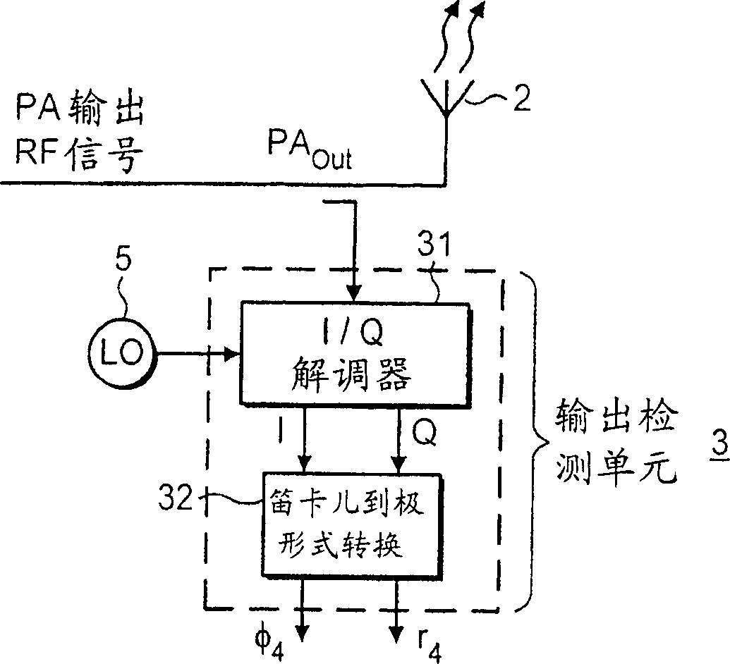
[0082] In an embodiment of the invention, an output detection unit 3 is provided for monitoring the power amplifier output signal and generating detected phase and amplitude (φ 4 , r 4 )Signal. A local oscillator (LO) 5 is provided to enable the output detection unit 3 to convert the RF power amplifier output signal to the digital baseband frequency of ...


PUM


Abstract

The invention relates to a method of adjusting a radio frequency signal produced by radio frequency circuitry in response to receipt of phase and amplitude control signals from digital baseband circuitry which operates to convert digital data signals into such phase and amplitude control signals. The phase and amplitude control signals are adjusted in the digital baseband circuitry in order to compensate for time alignment errors which occur in the radio frequency circuitry.

Description

technical field [0001] The present invention relates to communication systems, and more particularly to digital communication systems. Background technique [0002] Existing typical digital communication systems usually use non-constant envelope modulation schemes, for example, the new EDGE system uses 3π / 8-8PSK modulation. This means that part of the information is in the amplitude (envelope) of the transmitted signal and part is in the phase of the transmitted signal. In other words, this is a combination of amplitude modulation (AM) and phase modulation (PM). [0003] To handle amplitude modulation, the output power amplifier (PA) in a wireless transmitter must be linear, i.e., the output power of the PA (P out,PA ) and PA input power (P in,PA ) must be linear. Otherwise, AM-AM distortion will result, where the gain of the PA varies with the input amplitude. [0004] To handle phase modulation, the phase shift (Δφ) through the PA must be constant for all possible pow...

Claims


Application Information

Patent Timeline
Patent Type & Authority Patents(China)
IPC IPC(8): H03F1/32H04L27/36H03F1/30
CPCH03F2200/336H04L27/368H03F1/3247H03F1/3282
Inventor J·佩尔松
Owner TELEFON AB LM ERICSSON (PUBL)
Features
  • R&D
  • Intellectual Property
  • Life Sciences
  • Materials
  • Tech Scout
  • Unparalleled Data Quality
  • Higher Quality Content
  • 60% Fewer Hallucinations
Learn More