Method and apparatus for using regenerated liquid of waste sulfuric acid
A technology for regenerating liquid and waste sulfuric acid, which can be used in ion-exchange water/sewage treatment, etc., and can solve problems such as inability to meet requirements
- Summary
- Abstract
- Description
- Claims
- Application Information
AI Technical Summary
Problems solved by technology
Method used
Image
Examples
Embodiment 1
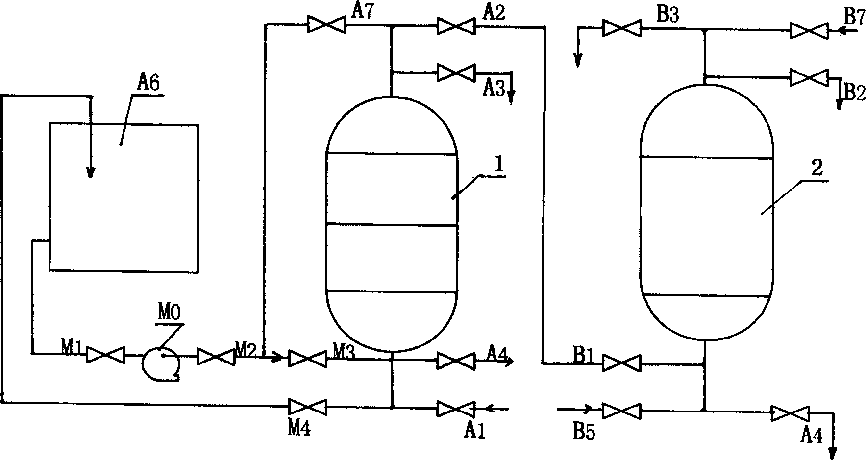
[0006] Example 1: figure 1 It is the monomer process flow chart applied in the floating cascaded ion exchanger system. The upper and lower parts of the pre-exchanger 1 are respectively provided with the feed valve A7 or M3 that can use the waste sulfuric acid regeneration liquid, and can use the waste sulfuric acid to regenerate. The liquid recovery valve M4 is connected to the pre-exchanger 1 through the pump M0, the recovery tank A6, the drainage valves A4, A3 and the phase pipeline to form a waste sulfuric acid regeneration liquid utilization device. In the floating cascaded ion exchanger, the regeneration liquid enters the exchanger from the feed valve B7 on the upper part of the post-stage ion exchanger through the pipeline, first passes through the strong cation exchange resin in the post-stage exchanger, and then passes through the front stage The strong and weak cation exchange resins in the exchanger are then discharged through the pipeline through the lower drain val...
Embodiment 2
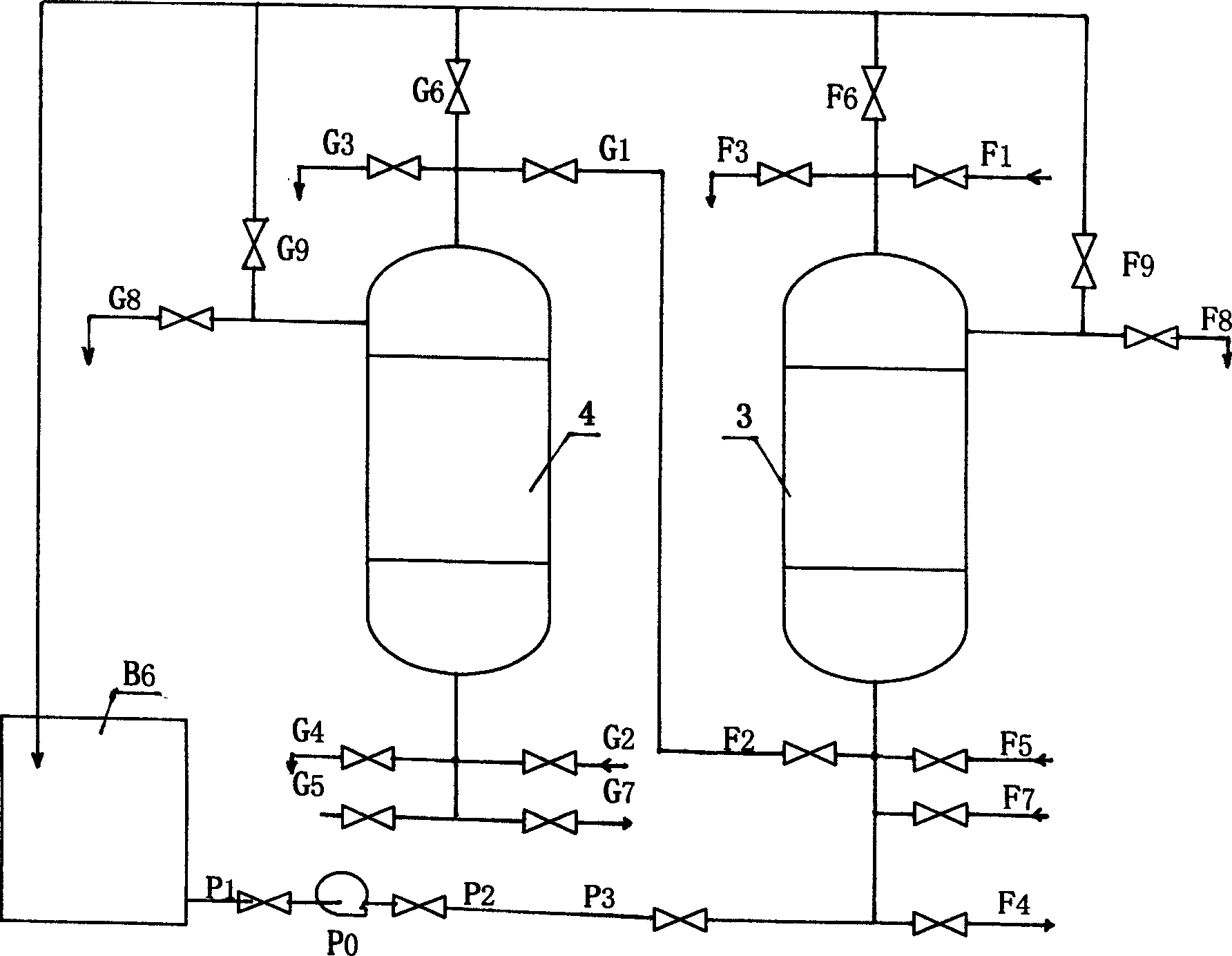
[0007] Example 2: figure 2 It is a fixed cascaded ion exchanger. In the lower part of the front-stage exchanger 3, there is a feed valve P3 for the regeneration liquid of waste sulfuric acid. On the upper part of the front-stage exchanger 3 and the rear-stage exchanger 4, there is a Waste sulfuric acid regeneration liquid recovery valves F6, F9, G6, G9. They are connected to the pre-exchanger 3 through the pump P0, the recovery tank P6, the drain valve F3 or F8 and the corresponding pipeline to form a waste sulfuric acid regeneration liquid utilization device. In the fixed cascaded ion exchanger, the regeneration liquid enters the exchanger from the feed valve G7 at the lower part of the post-stage ion exchanger through the pipeline, first passes through the strong cation exchange resin in the post-stage exchanger, and then passes through the front stage The weak cation exchange resin in the exchanger is then discharged through the pipeline through the drain valve F3 or F8. ...
Embodiment 3
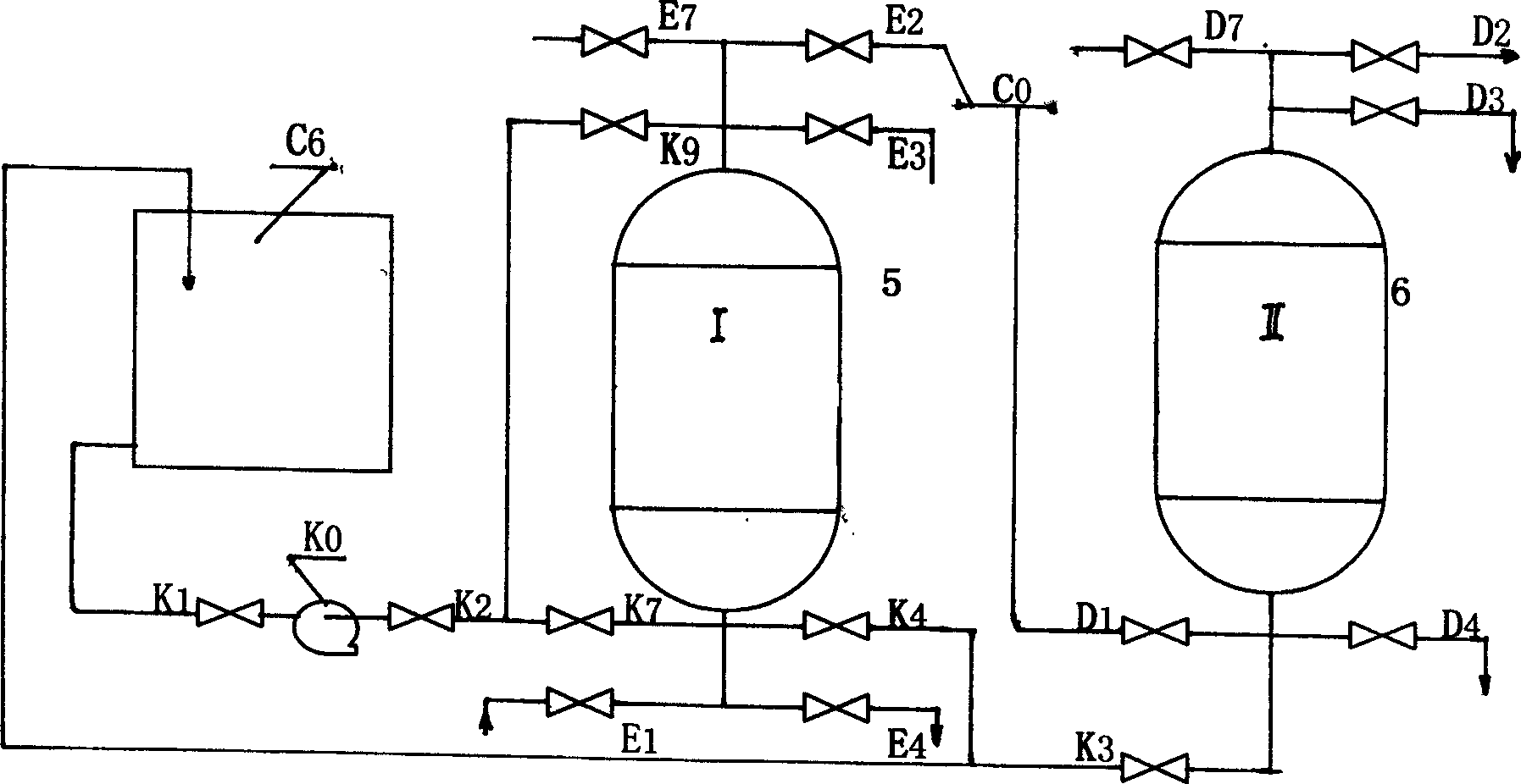
[0008] Example 3: image 3 It is a parent tube type cascaded ion exchanger. At the lower part of the front-stage exchanger 5 and the rear-stage exchanger 6, recovery valves K3 and K4 for regenerating liquid using waste sulfuric acid are respectively provided. , is provided with the waste sulfuric acid regeneration liquid feed valve K7 or K9, which are connected with the pre-stage exchanger 3 through the pump K0, the recovery tank C6, the drain valve E3 or E4 and the phase pipeline to form a waste sulfuric acid regeneration liquid for utilization device. In the parent tube type cascaded ion exchanger, the regenerated liquid enters the exchangers 5 and 6 from the feed valve E7 on the upper part of the front-stage ion exchanger and the feed valve D7 on the upper part of the rear-stage ion exchanger respectively, and passes through the pipeline. After the weak and strong cation exchange resins in the front and rear stage exchangers, they are discharged through the pipeline throug...
PUM
 Abstract
Description
Claims
Application Information
 - R&D
- Intellectual Property
- Life Sciences
- Materials
- Tech Scout
- Unparalleled Data Quality
- Higher Quality Content
- 60% Fewer Hallucinations
Browse by: Latest US Patents, China's latest patents, Technical Efficacy Thesaurus, Application Domain, Technology Topic, Popular Technical Reports.
© 2025 PatSnap. All rights reserved.Legal|Privacy policy|Modern Slavery Act Transparency Statement|Sitemap|About US| Contact US: help@patsnap.com


