
Passive optical network protection method

A passive optical network and optical network unit technology, applied in the protection field of passive optical network, can solve the problem of slow recovery time and achieve the effect of fast and effective protection

Inactive Publication Date: 2006-05-31
SHANGHAI JIAOTONG UNIV
View PDF0 Cites 0 Cited by
  • Summary
  • Abstract
  • Description
  • Claims
  • Application Information

AI Technical Summary

Problems solved by technology

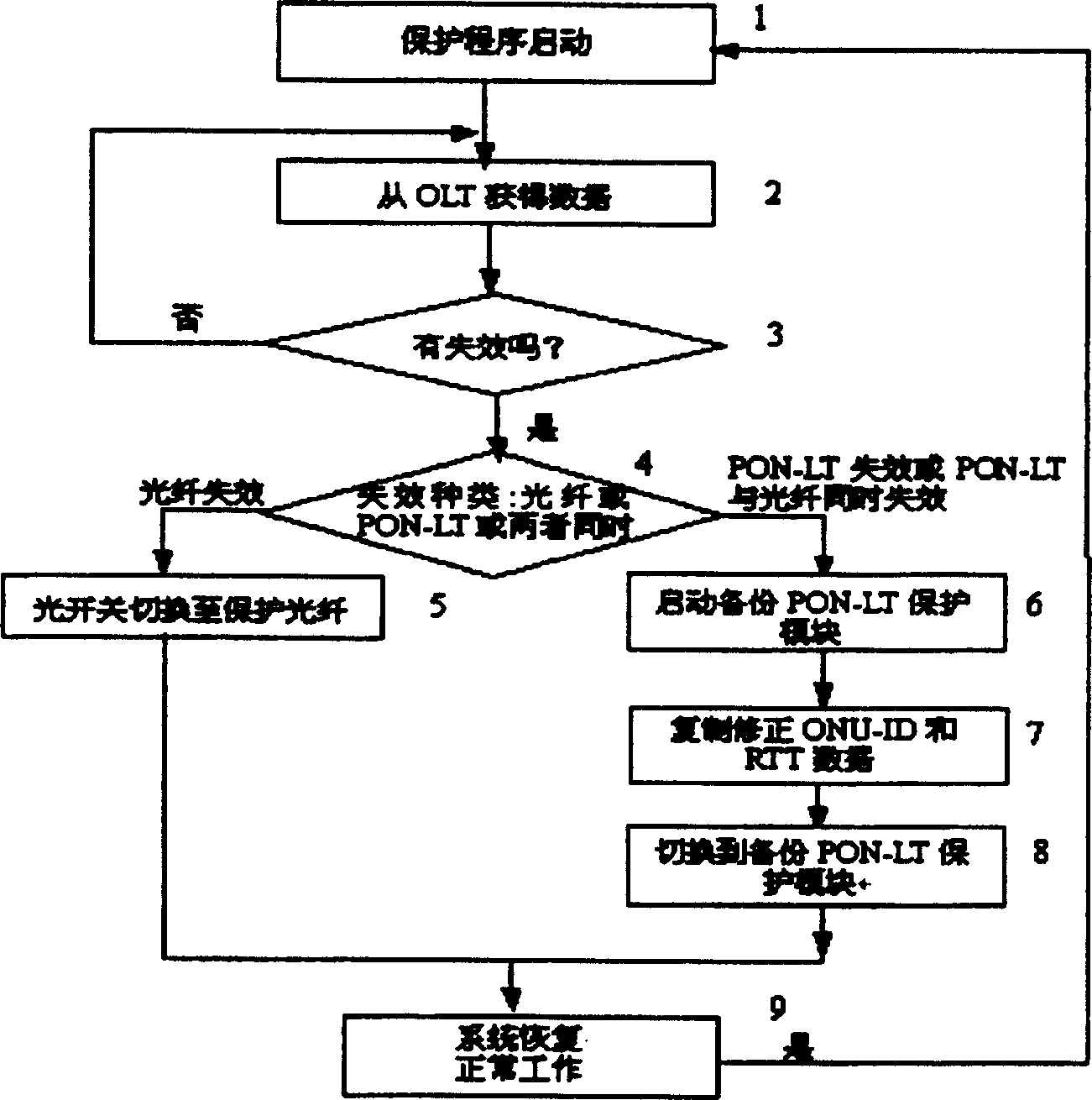
[0007] The purpose of the present invention is to propose an improved passive optical network protection method to solve the shortcomings of the existing protection methods that the recovery time of some failures is slow, so as to ensure that the system can return to normal within the protection time of the carrier level and meet the different requirements of customers.

Method used


Image

  • Passive optical network protection method
  • Passive optical network protection method
  • Passive optical network protection method

Examples


Embodiment Construction

[0018] In order to better understand the technical solutions of the present invention, the implementation manners will be further described below in conjunction with the accompanying drawings.

[0019] figure 1 It is a structural schematic diagram of the protection system of the present invention. The system is mainly composed of an optical line terminal (1), a working optical fiber (5), a protective optical fiber (6), a 2×N optical splitter (7), a working optical network unit (8), and an optical fiber (9). The optical line terminal (1) includes a control module (2), a PON-LT working module (3), a PON-LT protection module (4) and a 2×2 optical switch (10), and the control module (2) is connected through a control line The PON-LT work module (3) and the PON-LT protection module (4), the PON-LT work module (3) and the PON-LT protection module (4) are respectively connected to two of the 2×2 optical switches (10) The input port, the two output ports of the 2×2 optical switch (1...


PUM


Abstract

The protection system is composed of optical line terminal, work optical fiber, protection optical fiber, 2X2 optical branching device and work optical fiber network unit. The optical line terminal includes control module, PON-LT work module, PON-LT protection module and 2X2 optical switch. The control module possesses function of judging system crash. Based on diverse kinds of system crash, method of switching optical switch and protecting optical fiber can be utilized. Or, RTT data of PON-LT protection module round trip time measured in advance as well as corresponding optical network unit number ONU-ID data are copied in order to cancel procedure of distance measurement. Moreover, compensation and computed correction are carried out for new added optical network unit number data and corresponding round trip time. The procedure of distance measurement is also canceled, and rising speed for resuming protection of system.

Description

Technical field: [0001] The invention relates to a protection method for a passive optical network, which can recover to normal within a carrier-level protection time when a system fails, and belongs to the technical field of optical communication. Background technique: [0002] Recently, Passive Optical Network (PON, Passive Optical Network) has begun to attract people's attention. Passive optical network is proposed to solve the "last mile" problem. As we all know, in the access network and the local loop, the distribution of telephone copper wires and CATV coaxial cables has a great advantage in the last mile of residential areas. The passive optical network adopts a point-to-multipoint network structure. There are no active devices in the optical distribution network. Many users share the optical network unit, and many optical network units share the optical line terminal, thereby reducing the initial construction cost. Compared with active optical network and copper w...

Claims


Application Information

Patent Timeline
Patent Type & Authority Patents(China)
IPC IPC(8): H04B10/20H04B10/08H04Q3/52H04Q3/00H04B10/032
Inventor 赵焕东曾庆济池灏刘华王云
Owner SHANGHAI JIAOTONG UNIV
Learn More